Drawing Canvas
The drawing canvas is used to draw the building being modeled and for adding site objects. The following tools are available to aid in navigating the drawing canvas.
Drawing Canvas Navigation
|
|
Pan canvas

The pan canvas control in the upper left corner of the drawing canvas moves the point of view parallel to the 2D drawing plane along one of the cardinal directions. With the mouse, hold right-click and in any direction.
Use a, w, s, d keys to move the camera left, up, down or right, respectively.
Zoom canvas
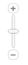
The zoom control aids in getting close-up view of the model or zoom out to extents of the model. Use mouse scroll up or down to zoom in or out.
Building North Indicator
A green line that runs through the origin of the drawing grid indicates building north, is also the positive –y axis. True north may be altered from Create Site > Site Definition Tools > Set Site North.
True North Indicator Line
A blue line that runs through the origin of the drawing grid indicates true north when it has been modified from Site Definition Tools. True North is displayed in 2D Plan View only when the Site has been rotated. It is displayed in all 3D views regardless of rotation.
Isometric View (3D views only)
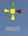
The control in the upper right hand corner of the 3D views sets the camera at the front, top, bottom, left, right, or back of the building. It provides a quick way to view extents of the building from those views. The front of the building provides the view from a point in the negative y-direction.
View Controls (lower left of screen)
Floor Plan View
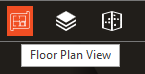
Click the Floor Plan View icon to enter 2D drawing mode. This viewing mode is intended to be used to draw the building floor by floor. It is the default view.
Level View
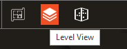
Click the Level View Icon to review 3D geometry of a single level. This viewing mode is intended to be used to verify geometry of a single level. Roofs are not displayed in this view.
Full Building View
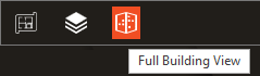
Click the Full Building Icon to review 3D geometry of the entire building. All levels and surfaces of the building are presented in 3D.This viewing mode is intended to be used to confirm that envelope of all levels in the building are aligned. Site objects are not presented in this view.
In the 3D views, the canvas is rotated around the centroid of the building using the mouse left-click and drag. Alternatively use arrow keys.
Level Controls
Terminology used in this section:
-
The active level is that which is being modified.
-
Base elevation is the elevation at the bottom of a level.
-
Terminating elevation is the elevation at the top of a level.
-
Rooms created on a level are bound by the base and terminating elevation.
-
Rooms can be created that span multiple levels.
-
Terminating elevation of a Level is the Base Elevation plus the Floor to Floor Height.
Level Selection
Level Selection Tool is used to select the active level. All Levels in the building are included in the list enabling quick navigation between levels.
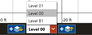
Alternatively, select a Level Name in the Tree.The active level remains active during Navigation to other section of the application. Navigation of Levels is used in Create Building Construction and Room Type views along with Zones and Zone Type Views. In Create Systems, this enables navigation for Assign Zones and Configure Zone Equipment.
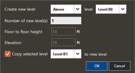
Create Level Above or Below
Clicking on the ‘+’ icon  to the right of the level indicator defaults inputs to add empty level(s) to the building above the active level.
Clicking on the ‘+’ icon  to the left of the level indicator defaults inputs to add empty level(s) to the building below the active level.
The Floor to Floor Height default value is that selected in User Preferences at the start of the project. However, this input can be set at time of level creation.
-
Default number of levels is 1.
-
Default Above/Below is based on the icon selected and may be modified while the dialogue is open.
-
Reference Level default is the active level.
Input Considerations
-
For level added above one with a flat roof, the flat roof is converted to inter-zone slab.
-
For level added above one with sloped roofs, the sloped roofs are not modified. This is obvious when viewing the 3D Full Building View.
-
A level including Non Standard Rooms cannot be copied. Only levels with standard rooms can be copied.
-
For level added under a below grade level, the ground contact slab is converted to inter-zone slab.
When a level is copied, all rooms assume constructions from the Construction Template applied to the Room Types assigned to the copied rooms. Overrides at the room level are not propagated with level copy operations. Best practices call for using templates to modify rather than local (room level) construction or other template properties. To modify the construction used for a room type, create a template in the library and apply to the desired Room Type. When copying levels, the new template is applied to rooms of the type with modified Construction template.
Copy Level
Check the box to copy selected level to new level. Duplicate(s) of the currently selected level is/are created when the OK button is clicked. Any level of the project may be copied above or below another level in the project. Use this control to insert a level between existing levels.
Create Level AT
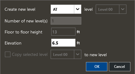
Create new level AT a specified elevation adds a drawing plane between the base and terminating elevation of a level. This action converts the rooms on the level to NonStandard Rooms – or rooms that span more than one level.
Levels may not be inserted AT elevation that do not bound levels. Therefore with AT selected, only the elevation is available for modification.
-
Elevation represents the absolute elevation at which a drawing plan will be inserted.
-
Default is the midpoint of the active level.
-
Elevations that are not within the building are not accepted.
This function might be used to create a mezzanine level after the building had already been created.
Delete Level
Click on the Delete Icon next to the level name in the Construction Tree to delete an entire level. Deletion of a level with NonStandard Rooms (rooms spanning multiple levels) results in reduction of height of rooms that traverse the deleted level.
Show Floor Plans
Use this control to hide plan images in views, when desired.
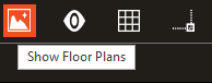
This control overrides the state of Show/Hide for each Plan image in the Construction Tree.
Show Shadows/Sun Settings
These controls are used to enable shadow casting based on solar position with location, time of day and year in 3D Level, 3D Full Building.
Show Shadows Checkbox
Check the box to enable shadow casting.
Time Slider
Drag the slider control or use the mouse scroll to adjust the time of day.
Month Slider
Drag the slider control to adjust the day/month within the year.
Sun Settings
Open the full control to specify exact time/date or solstice to render shading due to sun position.
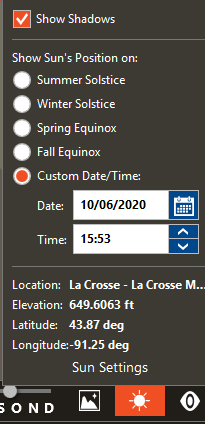
Input Considerations:
Solstice and Equinoxes are based on Northern Hemisphere. Surfaces that cast shadows include Walls, Opaque Doors, Slabs, Roofs, Fin/Overhang and Parapets.
In Level 3D View, even though roofs are not rendered, the shadows cast by roofs are still rendered. Shading due to Parapet and Overhang are not rendered because the roof is not rendered.
In Full Building 3D view, all shading is rendered for the Building. Site objects are not rendered in this view.
Use Site 3D View to view impact of shading due to Site Objects.
Building Visibility
Hide certain building elements during drawing or in 3D views to analyze specific geometry.
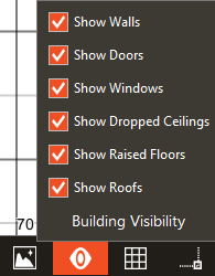
Show Walls
The ‘Show Walls’ checkbox toggles the display of walls on the drawing canvas.
Show Doors
The ‘Show Doors’ checkbox toggles the display of doors on the drawing canvas. While shadows are being rendered, glass doors are not hidden.
Show Windows
The ‘Show Windows’ checkbox toggles the display of windows on the drawing canvas. This does not include skylights. While shadow are being rendered, windows are not be hidden.
Show Dropped Ceilings
The ‘Show Dropped Ceilings’ checkbox toggles the display of ceilings on the drawing canvas. Drop Ceiling is rendered in 2D view as red diagonal lines. Plenum walls are not impacted by this setting.
Show Raised Floors
The ‘Show Raised Floors’ checkbox toggles the display of floors on the drawing canvas. Raised Floor is rendered in 2D view as blue diagonal lines.
Show Roofs
The ‘Show Roofs’ checkbox toggles the display of roofs on the drawing canvas. This has no impact when in 2D Floor Plan View unless the Roof Tool is active. Skylights are hidden with the roof.
Show Slabs
The ‘Show Slabs’ checkbox toggles the display of slabs in the 3D views only. Common usage of Hide Slabs is to see plan image in 3D views. This has no impact when in 2D Floor Plan View.
Wireframe Mode
The ‘Wireframe Mode’ checkbox toggles the display of slabs in the 3D views only.
Input Considerations
When tracing over a Plan Image, it can be useful to hide walls in order to determine where windows and doors should be placed. The cursor still snaps to the walls when hidden and cursor validation denotes placement is valid.
-
Hide Dropped Ceilings to view geometry in occupiable spaces in 3D Level View.
-
Hidden elements are still considered for all validation – if unable to make an action, ensure building elements are all shown.
Grid Settings
These controls are used to show/hide elements of the drawing canvas. Default values are taken from Settings > Default Grid Settings for most inputs.
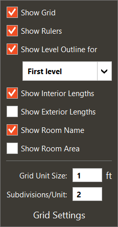
Show grid
The “Show Grid” check box toggles display of the grid.
Show rulers
The “Show Ruler” check toggles display of the drawing canvas rulers.
Show Level Outline for
The ‘Show Level Outline for’ check box toggles display of the reference level outline of the level selected in the Level Outline field.
Default: Level immediately below currently selected level for above-grade levels and above for below-grade levels.
Show Interior Lengths
The “Show Interior Lengths” check box toggles display of interior length labels displayed for each wall.
Show Exterior Lengths
The “Show Exterior Lengths” check box toggles display of exterior length labels displayed for each wall.
Show Room Name
The “Show Room Name” check box will toggle the room name labels displayed for each room.
Show Room Area
The “Show Room Area” check box will toggle the room area labels displayed for each room.
Grid Unit Size
Default = 1 foot or 1 meter. This input represents the smallest major grid size displayed at full zoom in.
Major grid lines/points can be snapped to.
Subdivisions/Unit
Default = 2
This input represents the number of minor grid lines displayed at full zoom in. Minor grid lines/points are not snapped to.
Input Considerations:
Grid lines and subsequent rulers are dependent upon zoom level. As zoom level is decreased, the lines and labels are updated accordingly in increments of 1, 2, 5, 10, 20, 50, regardless of minimum setting.
Inside and Outside dimensions are displayed during room creation regardless of the state of Show Interior and Exterior Lengths.
Snap Settings
Use to control what data is referenced for snapping.
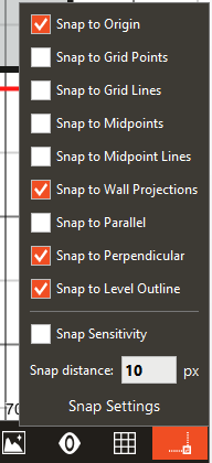
Defaults: Enabled snaps include Origin, Wall Projections, Perpendicular and Level Outline.
Snap to Origin
When selected, the drawing cursor snaps to the drawing canvas origin (x = 0, y = 0). A yellow indicator is displayed while cursor is snapped to origin while active snap to grid points is active.
Snap to Grid Points
When selected, the drawing cursor snaps to the intersections of major grid lines when creating geometry on the active level. Yellow indicator is displayed.
Snap to Grid Lines
When selected, the drawing cursor snaps to major grid lines. No indicator is displayed for this snapping option.
Snap to Midpoints
When this checkbox is selected, the drawing cursor snaps to the midpoint of existing walls. Windows/Doors snap to midpoint of walls upon which they are being placed. Yellow indicator is displayed and references only the active level.
Snap to Midpoint lines
When selected, the drawing cursor snaps to an imaginary line perpendicular to midpoint of walls. No indicator is displayed for this snapping option.
Dotted line below represents what would be snapped to along a line at center of north wall of Room 00-00, corresponding to the edge of Room 00-01 extending above and below when in view.
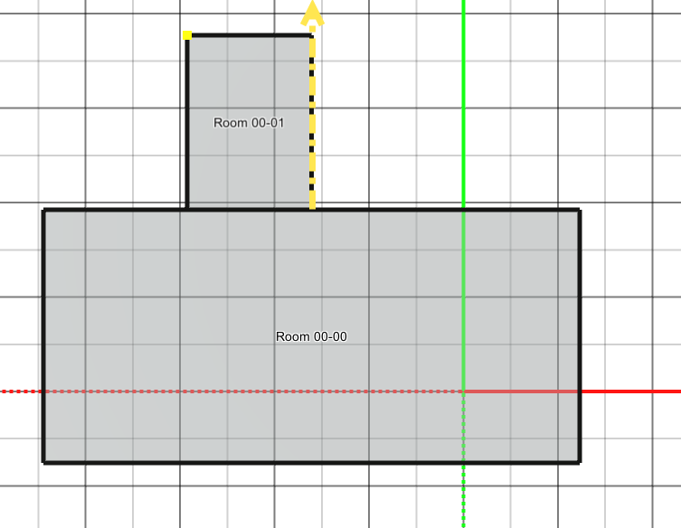
Snap to Wall Projections
When selected, the drawing cursor snaps to the projection of wall. A wall projection is a line that extends in space beyond the segment that is defined.
Often used when drawing the outline of a building to ensure that the envelope is aligned with rooms not immediately adjacent.
One example where this is useful would be on a recessed entryway. This snap aids in ensuring the walls are aligned on either side of the entry.
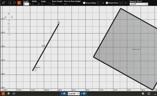
The west room’s north wall is snapped to the north wall of Room 00-00 while being created with the rectangle tool in the image below.
The polyline tool in the image below is used to initiate a wall from a point coincident with the projection of the north wall of Room 00-00.
The cursor snaps to the wall indicated in yellow.
Snap to Parallel
When selected, the drawing cursor snaps parallel with another wall while actively drawing. No indicator is displayed for this snapping option.
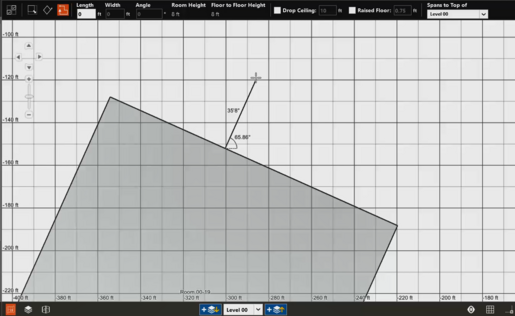
This is used to create wall segments that are parallel to other geometry in the building. Most commonly used when creating rooms with the Polyline Tool, but may also be used to set the Angle for the Angled Rectangle tool.
The example below shows the Polyline tool snapped to parallel wall of Room 00-16.
Snap to Perpendicular
When selected, the drawing cursor snaps perpendicular to previously created segment or to other existing walls in view. No indicator is displayed for this snapping option. However, for orthogonal walls, the angle indicator shows the angle with respect to positive x-axis.
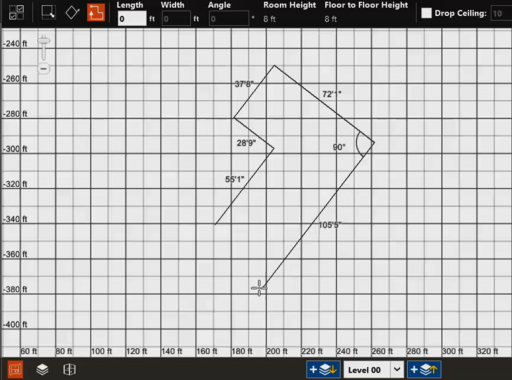
The most common usage of this is when creating polyline rooms that are not aligned with the axis to ensure each subsequent segment is at a right angle from the prior segment.
In the below example, each wall segment is 90 degrees from the prior segment.
It can also be used to ensure that a wall segment is perpendicular to other existing geometry, as shown below the segment is progress is at a right angle to the wall it bisects.
Snap to perpendicular snaps to all geometry in view, so where there are many wall surfaces at similar angles in a building, reduce the zoom level to omit unneeded references.
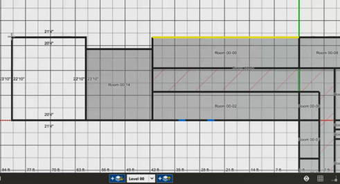
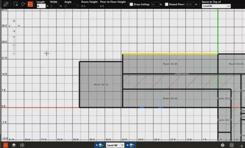
Snap to Level Outline
When selected, the drawing cursor snaps to geometry on the reference level indicated in Grid Settings >‘Show Level Outline For’.
Applicable snapping references include"
-
Walls,
-
Vertices,
-
Midpoint,
-
Midpoint Lines,
-
Parallel and Perpendicular wall projections on the reference levels.
Each that has a snapping indicator as denoted in prior sections of this document displays the cyan (light) blue indicator when active.
Snap Sensitivity
When selected, the snap radius of the cursor equals the number of pixels from Snap Distance Entry.
Default: Unchecked.
Snap distance
This entry sets distance in pixels the cursor will be ‘pulled’. A higher values means the cursor will snap to geometry that is farther away.
When there is more geometry, it can be useful to reduce this value. When set to high, there is less control as cursor snaps to things farther away.
|
Default: 15
|
|
Typical Range: NA
|
|
Min Max: 1 to 50
|
|
Units: NA
|
Input Considerations:
-
Edge and vertex snaps are always enabled and cannot be disabled.
-
Snapping indicators on the active level are yellow, where available
-
Snapping indicators on the reference level are cyan (light blue), where available.
-
Snapping is with respect to geometry in view on the canvas. When possible, pan or zoom the canvas to reduce the volume of data being referenced by snapping.
-
Snap to horizontal or vertical is enabled by holding the SHIFT key while a polyline segment is within 15 degrees of line parallel to x- or y- axis, respectively.
-
Settings are relevant to drawing tools and/or placement tools.
-
Use of snapping while creating rooms on other levels results in fewer surfaces in a project model, reducing calculation time.
-
Snapping to reference level should override reliance on plan images, especially when manual plan image scaling is used.
-
Combination of snap settings on the active and reference level is possible in some but not all cases.
-
Zoom in to reduce the number of references in complex models.