Design Psychrometrics
Design Psychrometrics Report
The Design Psychrometrics report displays the state points for each cooling coil. The information displayed for each coil is taken at the time of coil peak.
The Psychrometric State Point report is divided into two sections, one for Simulation Peak and one for Ideal Loads Peak. See the document titled “Ideal Peak Versus Simulation Peak” in the Getting Started Guide for a detailed discussion of these two approaches and their assumptions. By default, Simulation Peak is turned off and is not displayed.
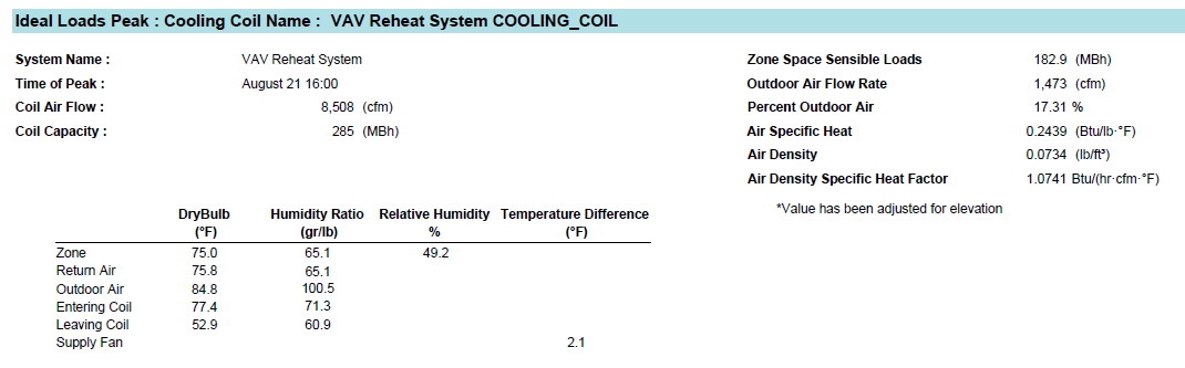
In the example above, relative humidity is around 49.2 percent. When considering relative humidity, we must always remember the effect dry bulb has on relative humidity. Relative humidity decreases as dry bulb increases, and relative humidity increases as dry bulb decreases. In other words, if the zone dry bulb were changed with the zone humidity ratio held constant, the zone relative humidity would change. For additional information and tools for understanding psychrometrics, please see the document titled “Psychrometrics” in the Getting Started Guide.
The air density specific heat factor is displayed. The user may replace the common 1.085 in the sensible heat equation with the value displayed above, which in this scenario is 1.0741. The entering coil conditions are calculated as the mixed air condition of the air at the time of coil peak. The leaving coil conditions are calculated based on the supply temperature entered in the system properties accounting for any components between the outlet of the cooling coil and the temperature sensor. For example, the desired supply air dry bulb is 55 °F, but a fan exist downstream of the cooling coil. The fan, being in drawn-through configuration, will add heat to the supply air stream. Therefore the cooling coil must overcool the air to offset the heat gain from the fan. In the example above, there was 2.1 °F fan heat; therefore, the leaving cooling coil temperature was 55 – 2.1 = 52.9 °F.
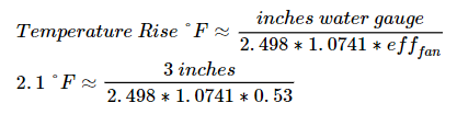
In the example above, the fan heat may be approximated in the IP form, using an Air Density Specific Heat Factor of 1.0741 btuh/cfm°F from the psychrometrics state point report:
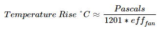
Likewise, the fan heat may be approximated in the SI form, using an Air Density Specific Heat Factor of 1201 J/m3K from the psychrometrics state point report:
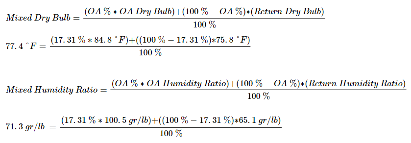
In the example above, the psychrometric state point report shows 17.31 % outdoor air. Using the mixed air equation, the entering state point can be confirmed, which verifies the ventilation load is accounted for in the Cooling Coils section of the System Component Summary report. Values are truncated in the reports from their actual values and may differ slightly.
The leaving cooling coil humidity ratio is based on the Trane empirical coil curves. In short, moisture is removed as the coil pushed the air toward the saturation curve. See the answer Load Design and Psychrometrics in the Getting Started Guide.
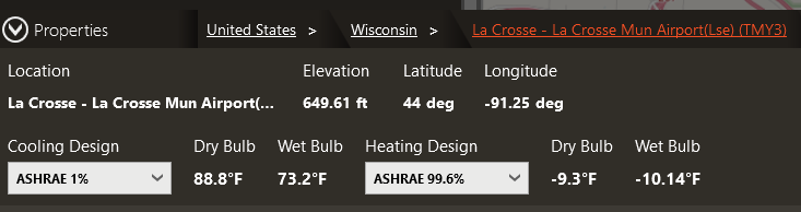
Notice the outdoor air condition is usually not the expected value on the Weather tab. In the example below, the input design weather was 88.8 °F dry bulb and 73.2 °F wetbulb (98.3 gr/lb). The cooling design outdoor conditions are not constant but vary throughout the day. In addition, the sun’s position moves throughout the day. It is common for the net peak coil load to not coincide with the peak outdoor air conditions, considering solar position and internal heat gain schedules.