General Settings
In the General Settings tab, the user defines the simulation time frame, reference calendar, time step, and heat balance algorithm. In addition the user can adjust advanced shadow settings or set the start/end for a daylight savings period.
Holidays Calendar
This calendar sets which days will be interpreted as holiday day-types as defined in the Schedules Library. Holidays often have significantly different operational characteristics and changing the calendar allows you to quickly account for regional holiday impacts. The icon next to the Calendar selection can take you to the Calendar Library where you can see the properties of an existing calendar or create your own.
Simulation Start/End
This field defines the starting month and day for the simulation run period in case you want to do an analysis for a specific period or to match the billing cycle. These dates need to match the selected Holidays Calendar.
Simulation Algorithm
The Simulation Algorithm provides a way to select what type of heat transfer algorithm will be used for calculating the performance of the building’s surface assemblies. There are two options:
● Conduction Transfer Function: is a sensible heat only solution and does not take into account moisture storage or diffusion in the construction elements
● Conduction Finite Difference selection is also a sensible heat only solution that does not take into account moisture storage or diffusion in the construction elements. This solution technique however uses a 1-D finite difference solution in the construction elements. The Conduction Finite Difference considers materials phase change as well as thermal conductivity.
Simulation Time Step
This field specifies the time step for the simulation. The value entered here is used in the Heat Balance Model calculation as the driving time step for heat transfer and load calculations. This value determines the number of time steps to use each hour. The choice made for this field has important implications for modeling accuracy and the overall time it takes to run a simulation. Here are some considerations when choosing a value:
● Simulation results are more accurate for shorter time steps
● Shorter time steps improve the numerical solution of the Heat Balance Model because they improve how models for surface temperature and zone air temperature are coupled together
● Longer time steps introduce more lag and lead to more a dampened dynamic response
● Simulation run time increases with shorter time steps
● Although the weather data files usually have hourly data, the program interpolates the weather data between data points for use at shorter time steps.
● For analysis of the maximum rates for electricity use or demand charges, the length of the time step needs to be consistent with the tariff’s demand window.
Minimum warm up Days
This field specifies the minimum number of “warm up” days before the program will check if it has achieved convergence and can thus start simulating the particular environment in question. Research into the minimum number of warm up days indicates that six warm up days is generally enough on the minimum end of the spectrum to avoid false predictions of convergence and thus to produce enough temperature and flux history to start simulation. It also was observed that convergence performance improved when the number of warm up days increased.
|
Default: 1
|
|
Min & Max: 1 < x < Maximum warm up Days
|
|
Typical Range: 6
|
|
Units: days
|
Maximum warm up Days
This field specifies the maximum number of “warm up” days that might be used in the simulation before “convergence” is achieved. The default number, 25, is usually more than sufficient for this task; however, some complex buildings (with complex constructions) may require more days.
|
Default: 25
|
|
Min & Max: Minimum warm up Days < x
|
|
Typical Range: 25
|
|
Units: days
|
Enable Daylight Savings
This field specifies whether to consider if there is a Daylight saving schedule. When the box is checked, you will need to select the Daylight Savings Start and Stop dates and the program will adjust the schedules by one hour.
Advanced Shadow Settings
Shadowing calculation is important for determining the amount of sun entering the building and therefore the amount of cooling or heating load needed for maintaining the building setpoints.
Calculation Frequency
This field will cause the shadowing calculations to be done periodically using the number in the field as the number of days in each period. Using the default of 20 days in each period is the average number of days between significant changes in solar position angles.
Calculation Method
This field is used to control how the solar, shading, and daylighting models are calculated with respect to the time of calculations during the simulation. The default and fastest method is Average over Days in Frequency. A more detailed and slower method is the Timestep Frequency method used for modeling dynamic fenestration and shading surfaces.
Polygon Clipping Algorithm
The internal polygon clipping method is used to treat overlapping shadows.
There are two available options:
1. Sutherland-Hodgman (default): is a simpler algorithm but it works well in cases where receiving surfaces (of shadows) are non-convex.
2. Convex Weiler- Atherton: is only accurate where both casting and receiving surfaces are convex.
Maximum Overlapping Shadows
This field will allow to increase the number of figures in shadow overlaps. Due to the shadowing algorithm, the number of shadows in a figure may grow quite large even with fairly reasonable looking structures. Of course, the inclusion of more allowed figures will increase calculation time. Likewise, too few figures may not result in as accurate calculations as desired.
Sky Diffuse Algorithm
Depending on the shadowing surfaces, there are two options:
● Simple Sky Diffuse Modeling (default): performs a one-time calculation for sky diffuse properties.
● Detailed Sky Diffuse Modeling is meant for surfaces where the shading transmittance varies. When the detailed modeling is selected, the Calculation Frequency should be greater than one. This option will increase calculation time.
Use Weather File Snow Indicators
Weather files can contain “snow” indicators. Snow changes the reflectivity of the ground and cascades changes of this reflectivity. Checking this field allows the weather file conditions to account for the snow if it is included in the weather file.
Use Weather File Rain Indicators
Weather files can contain “rain” indicators. Rain indicates wet surfaces which change the film convection coefficient for the surface. Checking this field allows the weather file conditions to account for that rain if it is included in the weather file.
Set All Radian Fractions to Zero

Shadowing calculation is importan
No = Do nothing (default).
Yes = Override all internal load radiation fractions to be zero. The override will not be observed in the user interface. The affect will be observed in the results.

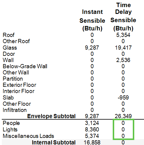
Purpose is to force all internal loads to be instant sensible or latent load on the zone load by component report. With all internal radiation removed from the model, the only remaining source of radiation would be the sun. Radiant loads affect Time Delay Sensible.

Set All Lost Heat Fractions to Zero

No = Do nothing (default).
Yes = Override all miscellaneous equipment load lost heat fractions to be zero. The override will not be observed in the user interface. The affect will be observed in the results.

Lost heat is energy consumed that does not create heat load. Setting this value to zero ensures all energy consumed produces heat load.
Set All Light Return Air Path Fractions to Zero

No = Do nothing (default).
Yes = Override all light return air path heat fractions to be zero. The override will not be observed in the user interface. The affect will be observed in the results.

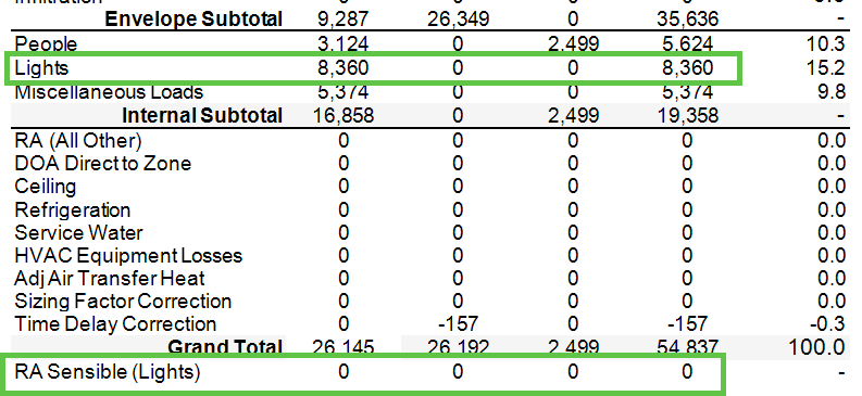
Purpose is to force the RA Sensible (Lights) row on the zone load by component report be zero and push the load up to the Lights category. RA Sensible (Lights) is not included for the zone airflow calculation, while the Lights category is included for the airflow calculation.

Round Up Occupancy

No = Do nothing (default).
Yes = Round each people load up to the next whole integer. The override will not be observed in the user interface. The affect will be observed in the results.
In the example below, 200 ft2/person was input. The result would have been 12.5 people in the room. The setting rounded the load to 13 people in the results.

Result can be observed on the Zone Load by Component Report.
