Loads by Component Reports
Load Component Reports
There are two load component reports, one for rooms and one for zones
-
Room Cooling & Heating Loads by Component
-
Zone Cooling & Heating Loads by Component
Both reports use the same formatting and will thus be described collectively below. The room level reports give the loads for individual rooms, and the zone level reports give the aggregate loads for the zone. The cooling load tables provide loads at the time of cooling peak and the heating load tables provide loads at the time of heating peak. These peak times are shown in the upper right-hand corner of the corresponding table. The outside and space conditions are reported in the Conditions at Time of Peak section. A positive value denotes a heat gain to the space and a negative value denotes a heat loss from the space.
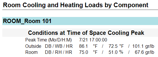
Conditions at Time of Peak
This section gives both the outside air and room conditions at the reported peak time. At the top left, we can see the outdoor air condition coinciding with the peak load conditions for this zone. The design weather is not held at one constant condition, but rather varies according to a design profile contained in the weather library. The assumption by the weather file is that the design condition occurs when the sun is high in the sky and not when the sun in low in the sky.
The room air conditions coinciding with the peak load of the room are shown. The example Room 101 below is 75°F drybulb and 51 percent relative humidity. The room relative humidity is determined by the internal latent loads and the supply air dewpoints. The room relative humidity is calculated from the supply air humidity ratio and internal latent loads.More detail can be found on the Psychrometric State Point report.
Load Component Table
The load component table shows the breakdown of loads in the zone according to surface or load type. The envelope loads are listed first according to surface type. The internal loads are listed second according to load type. Adjustments to the zone loads are listed third.
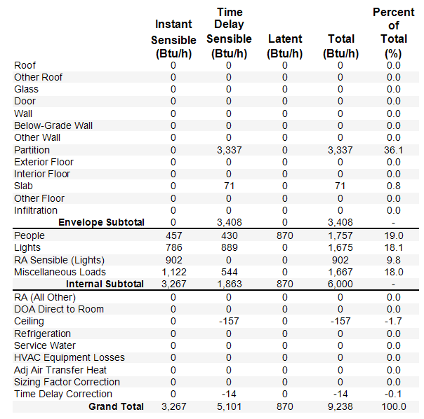
Instant sensible loads directly heat the air of the zone, while time delay sensible loads interact with the building’s mass prior to impacting the zone air. Wall conductions loads are contained in the Time Delay Sensible column because the heat must transfer from the outside air, through the exterior air film, through each layer of the wall, through the interior air film, and then to the air in the zone. Internal loads such as coffee makers instantly add heat and moisture to the air around them and would be instant sensible. Latent loads are listed in the third column, then total in the fourth column. Percentages are provided for the user’s benefit.
|
Component
|
Definition
|
|
Envelope Loads
|
|
|
Roof
|
Roof surface defined in Create Building
|
|
Other Roof
|
not yet supported
|
|
Glass
|
Windows, skylights, and glass doors defined in Create Building.
|
|
Door
|
Opaque doors defined in Create Building (Glass doors are in the glass category)
|
|
Wall
|
Exterior walls defined in Create Building for above ground levels
|
|
Below-Grade Wall
|
Exterior walls defined in Create Building for basement levels
|
|
Other Wall
|
not yet supported
|
|
Partition
|
Interior walls defined in Create Building
|
|
Exterior Floor
|
Floor exposed to outside air (such as a cantilevered space)
|
|
Interior Floor
|
Floors between rooms on different levels
|
|
Slab
|
Ground contact slab
|
|
Other Floor
|
not yet supported
|
|
Infiltration
|
Unconditioned outdoor air defined in the Airflows properties in Create Building
|
|
Internal Loads
|
|
|
People
|
People defined in the Internal Loads properties in Create Building
|
|
Lights
|
Portion of the lighting load to the space defined in the Internal Loads properties in Create Building
|
|
RA Sensible (Lights)
|
Portion of the lighting load to the return air defined in the Internal Loads properties in Create Building (see calculation method below)
|
|
Miscellaneous Loads
|
Miscellaneous loads defined in the Internal Loads properties in Create Building
|
|
Other Loads
|
|
|
RA ( all other)
|
Portion of the refrigeration load affecting the RA. Refrigeration loads are not yet supported so RA (All Other) is also not yet supported
|
|
DOA Direct to Zone
|
Load due to a Zone DOAS defined either on the Select Systems tab and serving a zone directly or defined on the Configure Systems tab and serving an individual zone level system. In both cases, the conditioned outdoor air is delivered directly to the zone so it imposes a load on the zone directly. The Multiple System and System level DOAS deliver conditioned outdoor air to the main system coils and therefore do not impose a load on the zone directly.
|
|
Ceiling
|
Ceiling load due to either a drop ceiling between a space and the plenum above, or a ceiling between a space and the space on the level above when there is no drop ceiling or plenum
|
|
Refrigeration
|
not yet supported
|
|
Service Water
|
not yet supported
|
|
HVAC Equipment Losses
|
not yet supported
|
|
Adj Air Transfer Heat
|
Load due to adjacent air being transferred between zones or systems from another room/zone into this room/zone. On the Room level reports, a value will appear here whenever there is adjacent air transfer from another room to this room. On the Zone level reports, there will only be a value here if adjacent air is being transferred from a different zone and not between rooms on the same zone
|
|
Sizing Factor Correction
|
This accounts for the sizing factor applied in the Load Design Parameters tab of Simulation Settings (see calculation method below)
|
|
Time Delay Correction
|
This accounts for the difference between the exactly calculated sensible load and the sum of the estimated sensible components from this report. For more information, see note in the calculations section below.
|
There are 5 columns in the table.
Instant Sensible
This is the sensible load to the space at the time of peak. This is the load that enters the space or is generated in the space at the peak hour.
Time Delay Sensible
This is the sensible load due to radiant components of the load. The radiant components of internal loads are defined in the internal load libraries and in the internal load templates. There are also radiant components of envelope loads. These radiant loads are absorbed by the surface in the space and retransmitted at later hours. The time delay sensible load is an estimate of the current hour’s load and previous hours’ loads that are impacting the space at the time of peak. For more details on these calculations, see the Energy Plus Engineering Reference Manual in section 24.2 Component Loads Summary.
Latent
This is the latent component of the load that impacts the space at the time of peak. The latent component of internal loads are defined in the internal loads library and can be edited in the internal load template in the project.
Total
This is simply the sum of the instant sensible, time delay sensible, and latent loads.
Percent of Total
This is calculated by (Percent of Total) = (Total)/(Grand Total)*100
Calculations
RA Sensible Lights
Sensible Load = Return air component of lighting load – RA exhaust
RA exhaust = (%OA/100) * airflow * specific heat of moist air * (return air dry bulb – room dry bulb)
Sizing Factor Correction
Heating Sizing Factor = (Grand Total in the Total column)/(Grand Total in the Total column – Sizing Factor correction)
Cooling Sizing Factor = (Instant Sensible + Time Delay Sensible – RA Sensible (Lights))/[ (Instant Sensible + Time Delay Sensible – RA Sensible (Lights)) – Sizing Factor Correction]
The sizing factor is defined on the Load Design Parameters tab of the Simulation Settings.
Time Delay Correction
During the calculation, the program goes through a zone heat balance for each zone for each time step. These calculations determine each component of each load in the zone. Technically these load component values could be used to populate this report however this is too much data to store during the calculation. After each time step calculation, only the zone load is stored. These zone loads are used to determine the peak zone load and peak time. So when this report is populated, those load components are no longer known and are therefore estimated at the peak hour. This time delay correction represents the difference between the actual calculated load and the sum of the estimated loads from this report.
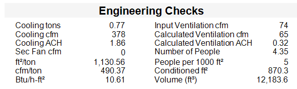
Engineering Checks
In the Engineering Checks at the bottom, we can see the capacity and airflows for this specific zone. The engineering checks are helpful to users who are looking for rule of thumb numbers, such as cfm/ton. If a specific rule of thumb number is desired, the engineer will have to back in a custom set of loads, schedules, and or supply air conditions to achieve those outcomes.
|
Cooling Tons:
|
This is the grand total Btu/h from this report converted to tons
|
|
Cooling cfm:
|
This comes from the airflow properties in the Create Building section if the user has entered a room level airflow. If it has been set to autosize, this will be the calculated airflow
|
|
Conditioned ft2
|
This is the conditioned square footage of this room/zone. This should match the calculated area that appears in the properties in the Create Building section
|
|
Ventilation cfm
|
Ventilation airflow from the 62.1 or the Sum Outside Air calculations. The ventilation input is in the Airflow properties of the Create Building section
|
|
ft2/ton
|
This is equal to the square footage divided by the tonnage on this report. The values may be a little off due to rounding.
|
|
Cfm/ton:
|
This is equal to the airflow divided by the tonnage on this report. The values may be a little off due to rounding.
|
|
Number of people:
|
Number of people defined in the internal load properties in the Create Building section
|
|
People per 1000 ft2
|
Using the same people density, how many people would there be in 1000 ft2. This value is useful when looking at some of the exceptions in ASHRAE Standard 90.1
|
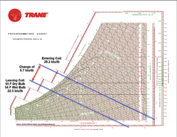
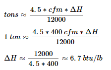
A typical value a user might look for is 400 cfm/ton. Such rule of thumb values have specific scenarios which they work, but rule of thumb values should not be expected in every scenario. The user can solve the coil capacity equation to see that 400 cfm/ton simply means an enthalpy change (dH) of 6.7 btu/lb across the cooling coil. Plotting the scenario on a psychrometric chart will reveal whether such an expectation is realistic or not. See the document titled “Psychrometrics” in the Getting Started Guide. There are many scenarios where 6.7 btu/lb across the cooling coil is not possible unless the user proactively forces the situation.
Below is a situation when this would occur.