Projects
Projects
Open Project
Allows you the ability to browse to the location of an existing project
Recent Projects
Any recent projects will be located on the left side of the opening screen, they will be underneath the New Project and Open Project Icons.
Tile will display building image, project name, and date project was created. A right click on the recent project tile displays some options for the project: Rename project, Remove project from the recent list, Copy project, and Delete project from the folder.
New Project
To Begin a new project in TRACE® 3D Plus, simply click the box with a “+” symbol on the far left-hand side of the main screen.
From this screen you can enter details of your project, enter your defaults, and Select Theme.
Create New Project
After clicking the + icon, the new project screen will appear. Here you can enter both the details of the project along with the default values.
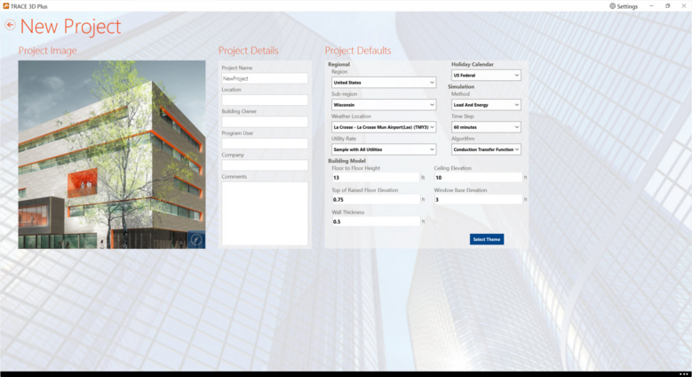
Project Image
A default project image will appear on the left-hand side of the screen. This image can be changed by clicking the pencil icon in the lower right-hand corner of the current image. You can then select an image from your computer. The selected image will appear in the tile of your main screen as a recent project.
Project Details
The Project Details section is where information used as a reference for the project can be entered. All data entered here will be shown in the Project Summary Report. These fields are not required.
Project Name
The project name will be displayed in the grey bar at the top of the screen.
Location
This is information entered regarding the location of the building. The location doesn't affect the weather location that is selected later for the simulation.
Building Owner
You can enter information about the owner of the building.
Program User
This is the person who is creating the load/energy model.
Company
You can enter information of the company performing the model.
Comments
Enter any additional information that might be useful for reference to your project.
Project Log
The Project Log gives you the ability to keep a running journal of changes made, or simply to keep notes on a specific project file and can be found on the App Bar. The window can be set as a fly-out or unpinned and opened as a separate window which can be moved to a separate area of the window or to a second monitor. The entry area is a free-text field and once saved, is immediately time-stamped and rendered uneditable. These saved entries can be deleted and the whole log can be exported to a .pdf, .txt, .doc or other word processing software formats. The User ID field allows you to use a unique identifier regarding their entries; helpful for projects with multiple users working on a single project.
Project Defaults
The project defaults are the baseline for the creation of each new project. This is where some basic parameters of the building are set when creating a new project. These parameters can be changed within the project but they allow you to set the prevailing parameters which can be changed as the project is constructed.
Regional
Region
This field allows you to filter the weather locations to the continent or sub-continent within which they are located.
Sub-Region
This field further filters the weather locations according to the country.
Weather Location
This is the actual weather location to be used for calculations.
Utility Rate
This section allows you to choose the utility rate to be used during the economic calculations.
Holiday Calendar
Simulation
Method
This section allows you to choose the calculation operating mode between Load Design or the full Energy and Economics.
Time Step
You will also be able to set how often calculations are performed which can be varied from one to 60 minutes.
Algorithm
The calculation algorithm options are as follows:
● Conduction Transfer Function: This option is a sensible heat only solution and does not take into account moisture storage or diffusion in the construction elements.
● Conduction Finite Difference Simplified: This algorithm uses a finite difference solution technique, the surfaces are divided into a nodal arrangement. The only output specific to Conduction Finite Difference solution (that is not include in other surface outputs) is node temperatures.
Building Model
Floor to Floor Height
The Floor-to-Floor Height is the vertical distance between floors including the plenum height and excluding the floor slab thickness. Enter the distance as measured from the floor slab surface to the bottom of the next higher floor slab surface - see the figure below. For the top floor, enter the distance between the floor slab surface and the internal roof surface.
This value is used in conjunction with the entered Ceiling Plenum Height and Floor Plenum Height to calculate:
● The percent of non-glass wall conduction load that is assigned to the return air path.
● The volume of the room - used to calculate any airflows entered with the units of air changes per hour.
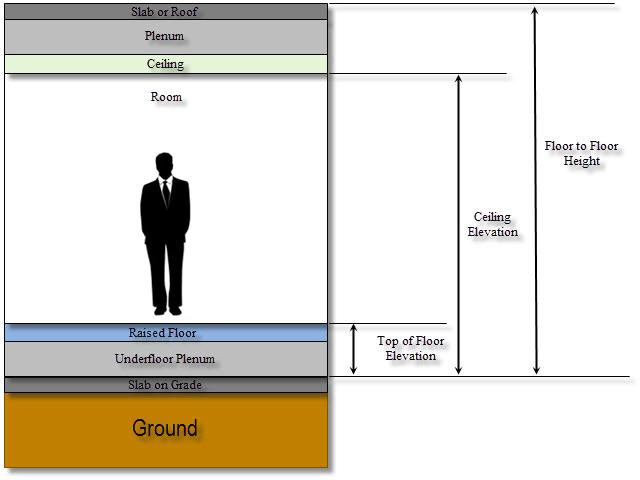
Ceiling Elevation
The Ceiling Height is the vertical distance between the floor slab surface and the ceiling. This value along with the Floor to Floor Height will dictate the ceiling plenum height:
Floor to Floor height – Ceiling Elevation = Ceiling Plenum Height
This value is used in conjunction with the entered Floor to Floor Height to calculate:
● The percent of non-glass wall conduction load that is assigned to the return air path.
● The volume of the room - used to calculate any airflows entered with the units of air changes per hour.
The plenum height is also used to decide if the roof conduction and solar heat gain loads are to be directed into the plenum or directly into the room. For example, if the plenum height is entered as zero, all the plenum loads are re-assigned to the room unless the Return Air Path has been entered as "Ducted".
Please note, upon an instance where the entered floor-to-floor height exceeds the ceiling height, the Drop Ceiling box will NOT automatically be checked and/or a drop ceiling will NOT automatically be added.
Top of Raised Floor Elevation
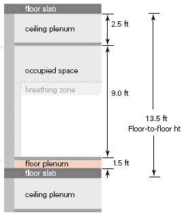
This value is the vertical height of the underfloor air distribution plenum. In the example shown below, the underfloor plenum height should be entered as 1.5 ft, while the Floor-to-Floor Height (entered on the Create Rooms – Rooms screen) should include the height of the underfloor plenum and be entered as 13.5 ft.
This field and the Conductive Resistance of Raised Floor field are used to calculate the amount of heat transferred into the underfloor plenum (and the associated heat loss from the room). Also, this field affects the exterior wall area exposed to the room versus the underfloor plenum. The underfloor plenum is assumed to be a dead air space unless the room has been assigned to one of the underfloor air distribution (UFAD) systems.
Wall Thickness
This field allows you to set the thickness of the walls in the program. This impacts the dimensional data. Since the dimensions set for each room are the interior room dimensions, the exterior dimensions will add the wall thickness to set those exterior room dimensions. This is the only place to set this dimension and it can only be set once. Once it is set for the project via the Project Defaults, it cannot be modified.
Window Base Elevation
This field is the vertical height from the bottom of the wall to the bottom of the window.
Select Theme
After the project description and defaults have been entered, continue to the next step of setting up a project by clicking on the "Select Theme" button in the lower right-hand corner of the screen.
Primary Navigation Bar
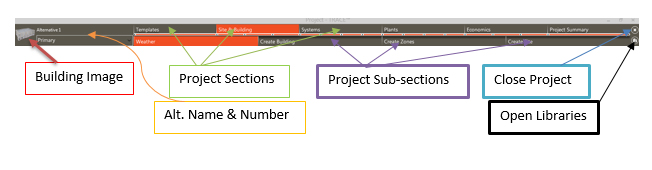
The top half of the navigation bar is divided into the major sections of the program which must be complete to run a full simulation.
The bottom half of the navigation bar contains the subsections of the major sections. For example under Site & Building is where you would select (or alter) Weather, Create Building, Create Zones, and have the option to Create Site around your building to simulate how nearby building will cast shade on your building.
Progress Bar
The Progress Bar is located in the navigation bar between the Sections and Subsections. It shows the number of subsections that each section contains..
Project Summary
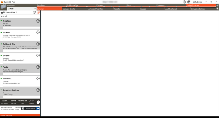
The project summary indicates whether or not a section is complete. The project will not calculate until all sections have a green check mark next to the section title.
The project summary gives a high level view of the project that was created including:
● Weather location and the stringency of the design conditions (ASHRAE 1% vs. 0.4% for example)
● How many rooms were created in the building, how many zones were created, and the gross floor area associated with the building
● How many systems were created and how many zones have been assigned to a system
● How many loops have been created and how many have been assigned
● A broad overview of the economics and utility rate structures applied
● Simulation settings along with time steps (6 minutes in this example) and which simulation will be performed (Load vs Energy & Economics)
● Status of results
● Any errors associated with the project