Screens
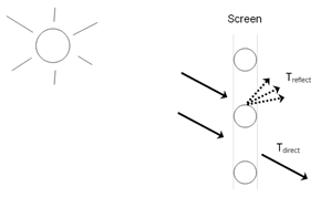
The window screen model assumes the screen is made up of intersecting orthogonally crossed cylinders. The surface of the cylinders is assumed to be diffusely reflecting, having the optical properties of a Lambertian surface. See figure below for a graphical representation.

The beam solar radiation transmitted through a window screen varies with sun angle and is made up of two distinct elements: a direct beam component and a reflected beam component. The direct beam transmittance component is modeled using the geometry of the screen material and the incident angle of the sun to account for shadowing of the window by the screen material. The reflected beam component is an empirical model that accounts for the inward reflection of solar beam off the screen material surface. This component is both highly directional and small in magnitude compared to the direct beam transmittance component (except at higher incident angles, for which case the magnitude of the direct beam component is small or zero and the reflected beam component, though small in absolute terms, can be many times larger than the direct beam component). For this reason, the reflected beam transmittance component calculated by the model can be a. disregarded, b. treated as an additive component to direct beam transmittance (and in the same direction), or c. treated as hemispherically diffuse transmittance based on a user input to the model.
The window screen “assembly” properties of overall beam solar reflectance and absorptance (including the screen material ‘cylinders’ and open area) also change with sun angle and are calculated based on the values of the beam solar transmittance components (direct and reflected components described above) and the physical properties of the screen material (i.e., screen material diameter, spacing, and reflectance). Transmittance, reflectance, and absorptance of diffuse solar radiation are considered constant values and apply to both the outside (front) and inside (back) surfaces of the screen. These properties are calculated by the model as an average value by integrating the screen’s beam solar properties over a quarter hemisphere of incident radiation. Long-wave emissivity is also assumed to be the same for both sides of the screen.
Window screens of this type can only be used on the outside surface of the window (“exterior screens”). When in place, the screen is assumed to cover all of the glazed part of the window, including dividers; it does not cover any of the window frames, if present. The plane of the screen is assumed to be parallel to the glazing.
The Screen material can be used to model wire mesh insect screens where the solar and visible transmission and reflection properties vary with the angle of incidence of solar radiation. For diffusing materials such as drapery and translucent roller shades it is better to use the Shade material. For slat type shading devices like Venetian blinds, which have solar and visible transmission and reflection properties that strongly depend on slat angle and angle of incidence of solar radiation, it is better to use Blind material.
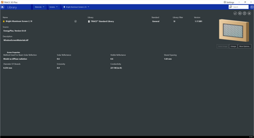
Screens properties

Method used for beam solar reflection
This input specifies the method used to account for screen-reflected beam solar radiation that is transmitted through the window screen (as opposed to being reflected back outside the building). Since this inward reflecting beam solar is highly directional and is not modeled in the direction of the actual reflection, you have the option of how to account for the directionality of this component of beam solar transmittance. Valid choices are Do not model, Model as direct beam (i.e., model as an additive component to direct solar beam and in the same direction), or Model as diffuse (i.e., model as hemisphericallydiffuse radiation). The default value is Model as diffuse.
Solar reflectance
This input specifies the solar reflectance (beam-to-diffuse) of the screen material itself (not the effective value for the overall screen “assembly” including open spaces between the screen material). The outgoing diffuse radiation is assumed to be Lambertian (distributed angularly according to Lambert’s cosine law). The solar reflectance is assumed to be the same for both sides of the screen. This value must be from 0 to less than 1.0. In the absence of better information, the input value for diffuse solar reflectance should match the input value for diffuse visible reflectance.
|
Default value:
|
blank
|
|
Min & Max:
|
0 <= x < 1
|
|
Typical Range:
|
N/A
|
|
Units:
|
N/A
|
Visible reflectance
This input specifies the visible reflectance (beam-to-diffuse) of the screen material itself (not the effective value for the overall screen “assembly” including open spaces between the screen material) averaged over the solar spectrum and weighted by the response of the human eye. The outgoing diffuse radiation is assumed to be Lambertian (distributed angularly according to Lambert’s cosine law). The visible reflectance is assumed to be the same for both sides of the screen. This value must be from 0 to less than 1.0.
If diffuse visible reflectance for the screen material is not available, then the following guidelines can be used to estimate this value:
Dark-colored screen (e.g., charcoal): 0.08 – 0.10
Medium-colored screen (e.g., gray): 0.20 – 0.25
Light-colored screen (e.g., bright aluminum): 0.60 – 0.65
|
Default value:
|
0.25
|
|
Min & Max:
|
0 <= x < 1
|
|
Typical Range:
|
N/A
|
|
Units:
|
N/A
|
Strand spacing
The spacing, S, of the screen material (m) is the distance from the center of one strand of screen to the center of the adjacent one. The spacing of the screen material is assumed to be the same in both directions (e.g., vertical and horizontal). This input value must be greater than the non-zero screen material diameter. If the spacing is different in the two directions, use the average of the two values. See image below for a graphic representation.
|
Default value:
|
blank
|
|
Min & Max:
|
0 <= x <= 1000
|
|
Typical Range:
|
N/A
|
|
Units:
|
mm; in
|
Diameter of strands
This is the diameter, D, of individual strands or wires of the screen material. The screen material diameter is assumed to be the same in both directions (e.g., vertical and horizontal). This input value must be greater than 0 and less than the screen material spacing. If the diameter is different in the two directions, use the average of the two values. See image above for a graphic representation.
|
Default value:
|
blank
|
|
Min & Max:
|
0 <= x <= 1000
|
|
Typical Range:
|
N/A
|
|
Units:
|
mm; in
|
Emissivity
Long-wave emissivity ε of the screen material itself (not the effective value for the overall screen “assembly” including open spaces between the screen material). The emissivity is assumed to be the same for both sides of the screen. For most non-metallic materials, ε is about 0.9. For metallic materials, ε is dependent on material, its surface condition, and temperature. Typical values for metallic materials range from 0.05 – 0.1 with lower values representing a more finished surface (e.g. low oxidation, polished surface). Material emissivities may be found in Table 5 from the 2005 ASHRAE Handbook of Fundamentals, page 3.9. The value for this input field must be between 0 and 1, with a default value of 0.9 if this field is left blank.
|
Default value:
|
0.9
|
|
Min & Max:
|
0 < x < 1
|
|
Typical Range:
|
N/A
|
|
Units:
|
N/A
|
Conductivity
This is the screen material conductivity in W/mK or Btu/hr-ft-F. This input value must be greater than 0.
|
Default value:
|
221 W/mK
|
|
Min & Max:
|
0 <= x <= 100,000
|
|
Typical Range:
|
N/A
|
|
Units:
|
W/mK; Btu/hr•ft•°F
|