System Component Summary
System Component Summary Report
System Summary
The System Type displays the category that the system library came from. The number of zones and rooms are defined in the Create Zones and Create Building tabs respectively in the Building & Site section.
A summary of the number and type of component is also given. This is determined by the system type and number of zones assigned to the system. For example, a zone level system with 10 zone assigned to it will have 10 sets of coils. More detail on these components is given in the following sections.
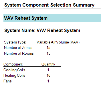
At the top, the number of rooms and zone is displayed. Next, the number of cooling coils, heating coils, and fans is displayed. In the example below, there are 15 rooms, which are each their own zone, one central cooling coil, one central heating coil, 15 VAV terminal box heating coils, and one central fan.
Cooling Coils
In the Cooling Coils section, the user can find the capacity, airflow, ventilation rate, and air state points for each cooling coil. The design cooling supply dry bulb is different from the cooling coil leaving dry bulb to overcome the heat generated by the fan. The coil location indicates if the coil is located at the system, zone, or room level. The system column gives the coil name, which can be changed in the Configure Systems and Configure Zone Level Equipment tabs of the Systems section. The system and zone columns indicate the zone or room in which the coil is located for zone and room level coils. The coil type is defined in the system properties for the coil.
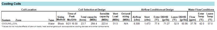
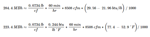
In the example below, there is a water-cooled cooling coil which peaked on August 21 at 16:00 (4:00 pm). The total capacity of the coil is 23.7 tons (284.4 MBh), of which 18.6 tons (223.4 MBh) is sensible cooling. The total ventilation load is 4.3 tons (51.5 MBh).
In an ideal situation, the total load would be equal to the sensible load plus the latent load. However, these equations constantly vary with temperature and pressure. Therefore, the user should not expect the sum of latent and sensible to perfectly match the total load. Notice the equations use the approximation symbol.
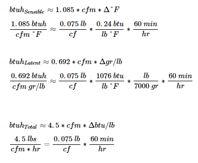
The IP forms of the coil sensible, latent, and total heat equations are shown below:
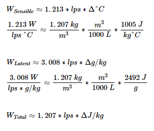
Likewise, the SI forms of the coil sensible, latent, and total heat equations are shown below:
In the example above, the total capacity can be hand verified. The entering air condition of 77.4°F / 71.27 gr/lb has an enthalpy of 29.56 btu/lb. The leaving air condition of 52.9°F / 60.86 gr/lb has an enthalpy of 21.96 btu/lb. The enthalpy change across the coil is approximately 29.56 btu/lb - 21.96 btu/lb = 7.60 btu/lb. Using the equations below, the total and sensible capacities can be confirmed.
The ventilation load can also be hand verified but requires examining the Psychrometric State Points report. See the Psychrometric State Points report for the mixed air calculations and air properties.
Additional notes on the Cooling Coils Section:
-
The sizing method is defined in the system sizing properties.
-
The capacities are at the time of peak from the load calculations
-
The capacities are based on the following:
-
Calculated without the effect of energy recovery or evaporative precooling.
-
Does not consider pull-up or pull-down loads, meaning each hour is assumed stready state.
-
Plenum loads are assumed to be loads direct to the space, and by default, are included in coil load sizing.
-
The return air does pick up heat in the plenum. The return air affected by the plenum load and the outdoor air mix to determine the coil inlet temperature
-
The "Include Plenum in Load Sizing" feature can be turned off by going to Project Summary > Simulation Settings > Load Design Parameters
-
Models ground contact as adiabatic
-
UFAD and DV systems are modeled as a well-mixed space
-
The Ov/under sizing columns show the difference between the assumed loads and the coil operation, such differences include:
-
Effect of energy recovery and evaporative cooling devices
-
Pull-up and pull-down loads being accounted for from thermostat schedules
-
Plenum loads if disabled
-
Models ground contact as user defined
-
UFAD and DV systems are modeled as stratified spaces
The over/under sizing is calculated as the difference between the total capacity reported here and the simulation load.
Over/undersizing can also be impacted by user-entered airflows in the room properties, system level airflows entered in the system properties, and coil capacities entered in the system properties.
The airflow is calculated at the time of coil peak based on the coil loads. If the system airflow has been input in the system sizing properties, that value will be reported. If the room airflow has been entered in the room properties, that value will be reported. If both have been entered, the system airflow will be reported for system level coils and the room airflow will be reported for zone and room level coils.
The entering coil conditions are calculated as the mixed air condition of the air at the time of coil peak. The leaving coil conditions are calculated based on the supply temperature entered in the system properties accounting for any components between the outlet of the cooling coil and the temperature sensor. For example, if 55 °F is entered for the cooling supply temperature in the system properties, but there is a draw through fan downstream of the cooling coil, the leaving cooling coil dry bulb will be less than 55 F. In the example above, there was 2.1 °F fan heat; therefore, the leaving cooling coil temperature was 55 – 2.1 = 52.9 °F.
If the coil is a chilled water coil, water entering and leaving temperatures as well as flow rate will be reported. The entering and leaving temperatures are defined in the plant properties. The flow rate is calculated based on the entering and leaving temperatures and the total coil load.
Heating Coils
In the Heating Coils section, the user can find the capacity, airflow, ventilation rate, and air state points for each heating coil. The coil location indicates if the coil is located at the system, zone, or room level. The system column gives the coil name, which can be changed in the Configure Systems and Configure Zone Level Equipment tabs of the Systems section. The system and zone columns indicate the zone or room in which the coil is located for zone and room level coils. The coil type is defined in the system properties for the coil.
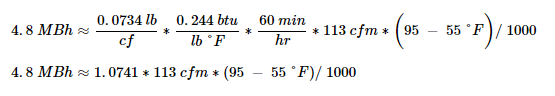
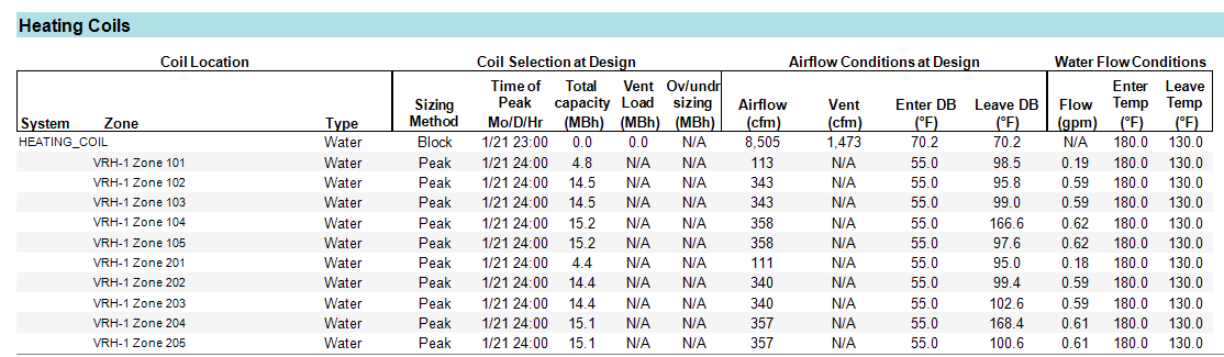
In the example below, there is one central water-heated heating coil and multiple VAV box heating coils which peaked around midnight in January. The main heating coil in this situation has zero capacity because the entering air temperature (70.2°F) is higher than the leaving air temperature (55°F), so the preheat coil has no load. Moving onto the Zone 101 terminal heating coil, the 4.8 MBh capacity can be confirmed using the sensible heat equation.
The sizing method is defined in the system sizing properties. The time of peak comes from the load calculations. The total capacity is calculated at the peak time. This capacity is based on the following:
-
Calculated without the effect of energy recovery or evaporative precooling
-
Does not consider pull-up or pull-down loads
-
Thermostat setpoint is held constant rather than using variable setpoints
-
Does not account for plenums
-
The plenum loads are assumed to be loads direct to the space
-
The return air and the outdoor air mix to determine the coil inlet temperature. The retur air does not pick up heat in the plenum so the coil inlet temperature will likely be lower
-
Models ground contact as adiabatic
-
UFAD and DV systems are modeled as a well-mixed space
The ventilation load shows the ventilation component of the total capacity. Keep in mind, the ventilation load is the total ventilation on the system. This may be conditioned by several different coils on the system. For example the preheat coil brings the ventilation up to a certain temperature and the reheat coils do the rest of the conditioning of the ventilation air.
The Ov/under sizing indicates over or undersizing of the coil as compared to the simulation load. The simulation load considers the following:
-
Calculated with the effect of energy recovery and evaporative precooling
-
Does consider pull-up and pull-down loads
-
Thermostat setpoints are based on input schedules
-
Does account for plenums
-
Models ground contact as user defined
-
UFAD and DV systems are modeled as stratified spaces
Over/undersizing can also be impacted by user-entered airflows in the room properties, system level airflows entered in the system properties, and coil capacities entered in the system properties.
The airflow is calculated at the time of coil peak based on the coil loads. If the system airflow has been input in the system sizing properties, that value will be reported. If the room airflow has been entered in the room properties, that value will be reported. If both have been entered, the system airflow will be reported for system level coils and the room airflow will be reported for zone and room level coils.
The entering coil conditions are calculated as the mixed air condition of the air at the time of coil peak for the first heating coil in the system. The entering coil conditions for subsequent heating coils in the system (such as a reheat coil) will be the leaving temperature of the previous heating coil in the system.
The leaving coil conditions are calculated based on the supply temperature entered in the system properties.
If the coil is a hot water coil, water entering and leaving temperatures as well as flow rate will be reported. The entering and leaving temperatures are defined in the plant properties. The flow rate is calculated based on the entering and leaving temperatures and the total coil load.
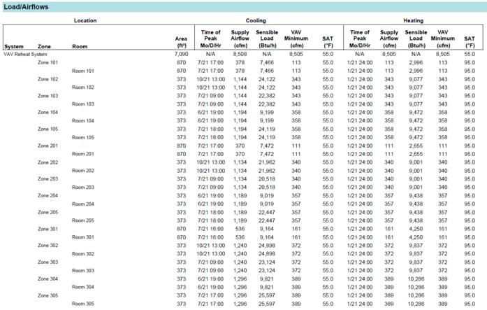
Load/Airflows
The Load/Airflows table provides the design sensible load, design supply air dry bulb, and design supply airflow of each room and zone. This table is useful for sizing supply diffusers to each room. The peak time comes from the load calculation. If the airflow to a room was hardset by the user, the hardset value will override the calculation. See the Zone Summary report for a different view for some of this information. The Load/Airflows report contains much of the same information.
Use Zone 101 for an example. The floor area of is 870 ft2. The time of the zone’s peak cooling load was July 21 at 17:00 (5:00 pm). The design cooling airflow is 378 cfm. The design heating airflow is 30 % of 378 cfm, equal to 113 cfm. In this situation, a VAV Reheat System was used with a default minimum stop of 30 %.
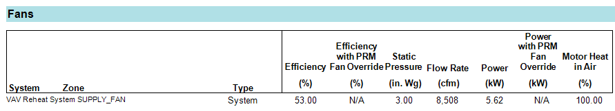
Fans
Fans at the system and zone level are reported here with their fan name, which can be changed in the system properties. The Type column indicates whether the fan is at the system level or the zone level. The fan efficiency is entered in the system properties. If the fan full load energy rate is entered, the actual fan efficiency is calculated using the fan full load energy rate and static pressure. If the fan full load energy rate is set to autosize, the entered fan efficiency is used.
The Fans section shows the peak airflow experienced by each fan. Here we see a summary of fan efficiency, peak airflow, static pressure, peak power, heat pickup, and whether the fan is applying the ASHRAE 90.1 performance rating method. To verify the fan power, we would apply the fan power equation: (8508 cfm x 3 inch) / (8.57 x 0.53) = 5620 watts (5.62 kW). 8.57 is a factor for unit conversions. See the system properties for the corresponding inputs. Below, the net efficiency (effnet) is 53 %.
The electric power is based on the power equation and does not account for other factors involved in sizing circuits. Always consult a licensed electrical engineer for sizing circuits!
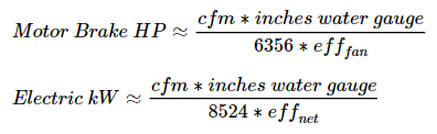
For standard air, the IP forms of the fan power equation are:
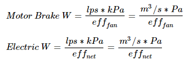
Likewise, the SI forms of the fan power equation are shown below, with the SI form equal to unity when efficiency (eff) is 100 %:
Pumps
The pumps section gives the name of the pump which can be edited in the Plants section. The type of pump is either constant or variable speed. The control is either Intermittent or Continuous as defined in the Flow Control field of the pump equipment library. Head is the pump head defined in the plant properties for the pump component. The flow is calculated using the plant entering and leaving temperatures and the load on the loop.
The pump power is calculated using the full load energy rate defined the pump properties and the motor efficiency defined in the pump equipment library. The power per flow is simply a ratio of the reported pump power and flow through the loop. To verify the pump power, we would apply the pump power equation: (37.78 gpm x 26 psig) / (2.3 x 0.90) = 475 watts (0.475 kW). 2.3 is a factor which includes unit conversions. See the plant properties for the corresponding inputs.
The electric power is based on the power equation and does not account for other factors involved in sizing circuits. Always consult a licensed electrical engineer for sizing circuits!
For water, the IP forms of the pump power equation are:
Likewise, the SI forms of the pump power equation are shown below, with the SI form equal to unity when efficiency (eff) is 100 %:
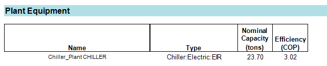
Plant Equipment
This section gives the name of the plant which can be edited in the Plants section. The type column indicates what type of equipment is on the plant (i.e. chiller, boiler etc.) The nominal capacity is either the calculated capacity based on the loads on the plant or the user-entered capacity in the plant component properties if it is not set to autosize. The efficiency is the user-entered efficiency from the component properties in the Plants section. For more details, see the Plant Summary Report.
Always consult a licensed electrical engineer for sizing circuits!