Trace 3D Plus
User Guide
 
×


Absorption Chillers
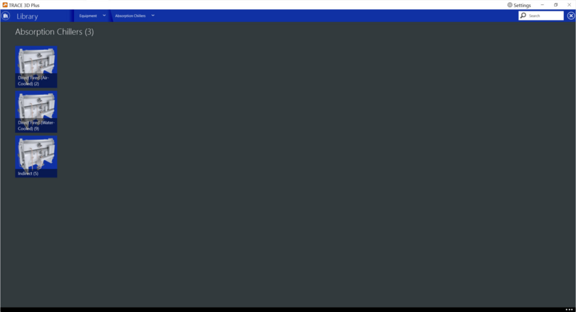
Absorption chillers use heat to drive the refrigeration cycle, they produce chilled water while consuming just a small amount of electricity to run the pumps on the unit. Absorption chillers generally use steam or hot water to drive the lithium bromide refrigeration cycle but can also use other heat sources. There are three types of Absorption chillers in this library.


Direct Fired Absorption Chillers (Air-cooled and Water-cooled)
Direct-fired absorption chillers use a natural gas burner to produce chilled water. The chiller uses natural gas or other fuels to fire the absorption refrigeration cycle. They can be air cooled or water cooled. This type of chiller-heater can provide simultaneous heating and cooling. During simultaneous operation, the heating capacity is reduced as the cooling load increases.
 
 
Product tab
 
Nominal Cooling Capacity
Default: Auto Size
Typical Range: Auto Size
Min Max: -999,999 to 999,999
Units: W; kW; tons; Btuh; Mbh
This numeric field contains the nominal cooling capacity of the chiller.
 
Nominal Heating Capacity
Default: 80% Clg Capacity
Typical Range: 0 to 100
Min Max: 0 to 100
Units: % Clg Capacity
This fraction represents the heating capacity as a percentage of the cooling capacity at rated conditions.
 
Full Load Power in Cooling
Default: 1% Clg Capacity
Typical Range: 0 to 100
Min Max: 0 to 100
Units: % Clg Capacity
This field represents the ratio of the instantaneous electricity used divided by the cooling capacity at rated conditions. If the chiller is both heating and cooling, only the greater of the computed cooling and heating electricity is used.
 
 
Full Load Power in Heating
Default: 0.5% Htg Capacity
Typical Range: 0 to 100
Min Max: 0 to 100
Units: % Htg Capacity
This field represents the ratio of the instantaneous electricity used divided by the nominal heating capacity. If the chiller is both heating and cooling, the greater of the cooling electricity and heating electricity is used.
 
Optimum Part Load Ratio
Default: 100
Typical Range: 0 to 100
Min Max: 0 to 100
Units: %
This is the part load ratio at which the chiller performs at its maximum COP. It represents the most desirable operating point for the chiller.
 
Sizing Factor
Default: 100%
Typical Range: 0 to 100
Min Max: 0 to 100
Units: %
This field allows you to specify a sizing factor for this chiller. The sizing factor is used when the chiller is autosize. The sizing factor affects the following calculations: Nominal Cooling Capacity, Design Chilled Water Flow Rate, Design Condenser Water Flow Rate and Design Hot Water Flow Rate. Sizing Factor allows to size a component to meet part of the design load while continuing to use the autosizing feature.
 
 
Design Water Temperatures
Design Entering Condenser Water Temperature
Default: 84.2°F (29°C)
Typical Range: 82 to 86°F (28 to 30°C)
Min Max: -130 to 158°F (-90 to 70°C)
Units: °F; °C
This field represents the temperature of the water entering the chiller’s condenser when operating at design conditions. For Water Cooled Chillers, this is the temperature delivered by the cooling tower.
 
Design Leaving Chilled Water Temperature
Default: 44.6°F (7°C)
Typical Range: 43 to 45°F (6.11 to 7.22°C)
Min Max: -130 to 158°F (-90 to 70°C)
Units: °F; °C
This field represents the temperature of the water leaving the evaporator of the chiller when operating at design conditions
 
Condenser Temperature Type
Default: Entering Temperature
Typical Range: N/A
Min Max: Entering temperature, Leaving Temperature
Units: N/A
This field determines if the temperature dependent performance curves have on the x axis the Leaving or Entering condenser temperature. Manufacturers express the performance of their chillers using either the leaving condenser water temperature (to the tower) or the entering condenser water temperature (from the tower).
 
 
Leaving Chilled Water Temperature Low Limit
Default: 35.6°F (2°C)
Typical Range: 34 to 36°F (1.11 to 2.22°C)
Min Max: -130 to 158°F (-90 to 70°C)
Units: °F; °C
This field is the chilled water supply temperature below which the chiller will shut off.
 
Fuel
Fuel Type
Default: Natural Gas
Typical Range: N/A
Min Max: N/A
Units: N/A
This field determines the type of fuel that the chiller uses. The available options are: Electricity, Diesel, Gasoline, Natural Gas, Coal, Propane Gas, Fuel Oil1 and Fuel Oil2.
 
Full Load Fuel Rate in Cooling
Default: 97 % Clg Capacity
Typical Range: 90 to 100%
Min Max: 0 to 900
Units: % Clg Capacity
This field represents the ratio of the instantaneous cooling fuel used divided by the cooling capacity at rated conditions.
 
Full Load Fuel Rate in Heating
Default: 125% Htg Capacity
Typical Range: 100 to 125%
Min Max: 0 to 900
Units: % Htg Capacity
This field represents the ratio of the instantaneous heating fuel used divided by the nominal heating capacity.


Curve tab


Cooling Mode sub tab
 
Capacity Curve
This biquadratic curve shows the percentage of full cooling capacity as a function of the condenser fluid temperature and the leaving chilled water temperature. Inputs consists of two independent variables, six coefficients, and min and max values for each of the independent variables. The equation for the capacity curve is:
Where:
Z = Cooling Capacity
C1 to C6 = coefficients
X = Condenser temperature
Y = Chilled Water Temperature
 
The curve has the following fields:
X Axis:
Condenser fluid temperature (°F, °C). Depending on the input for Condenser Temperature Type on the product’s tab, this axis will be either the Leaving or Entering Condenser Fluid temperature.
Y Axis:
Cooling Capacity (%).
Tchw,l Min / Max :
Minimum and maximum temperature values (°F, °C) for the Chilled water leaving temperature variable. These values determine the three chilled water temperatures plotted, one is the maximum, one is the minimum and the last one is the midpoint between them.
Tcond,l Min / Max:
Minimum and Maximum temperature values (°F, °C) for the Condenser Temperature variable.
 
 
Fuel Input Curve
This biquadratic curve represents the chiller’s fuel consumption at full load as a function of the condenser fluid temperature and the leaving chilled water temperature.  Inputs consists of two independent variables, six coefficients, and min and max values for each of the independent variables. The equation for the capacity curve is:
Where:
Z = Fuel Consumption
C1 to C6 = coefficients
X = Condenser temperature
Y = Chilled Water Temperature
 
The curve has the following fields:
X Axis:
Condenser fluid temperature (°F, °C). Depending on the input for Condenser Temperature Type on the product’s tab, this axis will be either the Leaving or Entering Condenser Fluid temperature.
Y Axis:
Fuel Consumption (%).
Tchw,l Min / Max :
Minimum and maximum temperature values (°F, °C) for the Chilled water leaving temperature variable. These values determine the three chilled water temperatures plotted, one is the maximum, one is the minimum and the last one is the midpoint between them.
Tcond,l Min / Max:
Minimum and Maximum temperature values (°F, °C) for the Condenser Temperature variable.
 
 
Fuel Capacity Curve
This quadratic curve represents the chiller’s fuel consumption at part load with operating temperatures at design values. The equation for the Fuel Capacity Curve is:
Where:
y = Fuel Consumption
C1 to C3 = coefficients
X = Part Load
 
The curve has the following fields:
X Axis:
Part Load (%)
Y Axis:
Fuel Consumption (%).
Cycle Point:
Represents the percentage (%) of full load capacity at which the equipment will turn on and off (cycle) to satisfy the load.
 
 
Ambient Relief Curve
This biquadratic curve represents chiller’s electric consumption at full load as a function of the condenser fluid temperature and the leaving chilled water temperature. Inputs consists of two independent variables, six coefficients, and min and max values for each of the independent variables.  The equation for the capacity curve is:
Where:
Z = Chiller’s electric consumption (%)
C1 to C6 = coefficients
X = Condenser temperature
Y = Chilled Water Temperature
 
The curve has the following fields:
X Axis:
Condenser fluid temperature (°F, °C). Depending on the input for Condenser Temperature Type on the product’s tab, this axis will be either the Leaving or Entering Condenser Fluid temperature.
Y Axis:
Chiller's electric consumption (%).
Tchw,l Min / Max :
Minimum and maximum temperature values (°F, °C) for the Chilled water leaving temperature variable. These values determine the three chilled water temperatures plotted, one is the maximum, one is the minimum and the last one is the midpoint between them.
Tcond,l Min / Max:
Minimum and Maximum temperature values (°F, °C) for the Condenser Temperature variable.


Electric Power Curve (Capacity Power Curve)
This quadratic curve represents the chiller’s electric consumption at part load with operating temperatures at design values.
The equation for the Fuel Capacity Curve is:
Where:
y = Chiller’s electric consumption (%)
C1 to C3 = coefficients
X = Part Load
 
The curve has the following fields:
X Axis:
Part Load (%)
Y Axis:
Electric Consumption (%).
Cycle Point:
Represents the percentage (%) of full load capacity at which the equipment will turn on and off (cycle) to satisfy the load.


Heating Mode sub tab
 
Heating Capacity Power Curve
This quadratic curve represents the chiller’s heating capacity as a function of its cooling capacity when the chiller is simultaneously cooling and heating. 
The equation for the Heating-Cooling Capacity Curve is:
Where:
y = Heating Capacity (%)
C1 to C3 = coefficients
X = Cooling Capacity (%)
 
The curve has the following fields:
X Axis:
Cooling Capacity (%)
Y Axis:
Heating Capacity (%).
Capacity Min/Max:
Minimum and maximum Cooling capacity of the chiller.
 
 
Heating Fuel Power Curve
This quadratic curve represents the chiller’s fuel consumption as the heating load varies when the chiller is operating only as heater.
The equation for the Heating Fuel Power Curve is:
Where:
y = Fuel Consumption during heating mode (%)
C1 to C3 = coefficients
X = Heating Part Load (%)
 
The curve has the following fields:
X Axis:
Heating Part Load (%)
Y Axis:
Fuel Consumption during heating mode (%).
Load Min/Max:
Minimum and maximum Heating load of the chiller.


Indirect Absorption Chillers
Indirect-fired absorption chillers use a waste or generated steam or hot water to produce chilled water. The chiller uses steam to fire the absorption refrigeration cycle.


Product tab
 
Nominal Cooling Capacity
Default: Auto Size
Typical Range: Auto Size
Min Max: 0 to 999,999
Units: W; kW; tons; Btuh; Mbh
This numeric field contains the nominal cooling capacity of the chiller.
 
 
Optimum Part Load Ratio
Default: 100
Typical Range: 0 to 100
Min Max: 0 to 100
Units: %
This numeric field contains the chiller’s optimum part-load ratio. This is the part-load ratio at which the chiller performs at its maximum COP.
 
 
Sizing Factor
Default: 100%
Typical Range: 0 to 100
Min Max: 0 to 100
Units: %
This field allows you to specify a sizing factor for this chiller. The sizing factor is used when the chiller is autosize. The sizing factor affects the following calculations: Nominal Cooling Capacity, Nominal Absorption pump power, Design Chilled Water Flow Rate, Design Condenser Water Flow Rate and Design Generator Fluid Flow Rate. Sizing Factor allows to size a component to meet part of the design load while continuing to use the autosizing feature.
 
Absorption Pump
Full Load Power
Default: Auto Size
Typical Range: Auto Size
Min Max: 0 to 999,999
Units: W; kW; Btuh; Mbh
This field represents the nominal pumping power of the chiller.
 
 
Design Water Temperatures
Design Entering Condenser Water Temperature
Default: 86°F (30°C)
Typical Range: 86°F (30°C)
Min Max: -130 to 158°F (-90 to 70°C)
Units: °F; °C
This field represents the temperature of the water entering the chiller’s condenser when operating at design conditions. This is the temperature delivered by the cooling tower.
 
Entering Condenser Water Temperature Low Limit
Default: 59°F (15°C)
Typical Range: 59°F (15°C)
Min Max: 59°F (15°C)
Units: °F; °C
This field contains the chiller’s condenser entering water temperature lower limit. No correction to chiller capacity is made for low condenser entering water temperatures.
 
Leaving Chilled Water Temperature Low Limit
Default: 41°F (5°C)
Typical Range: 41°F (5°C)
Min Max: 41°F (5°C)
Units: °F; °C
This field contains the chiller’s evaporator leaving water temperature lower limit. No correction to chiller capacity is made for low evaporator leaving water temperatures.
 
Entering Generator Fluid Temperature Low Limit
Default: 86°F (30°C)
Typical Range: 86°F (30°C)
Min Max: 86°F (30°C)
Units: °F; °C
This field contains the generator’s entering water temperature lower limit.  This field is not used if the chiller is connected to a steam plant in the project.
 
 
Steam Operating Conditions
Leaving Subcooling Temperature
Default: 33.8°F (1°C)
Typical Range: 33.8°F (1°C)
Min Max: 32 to 68°F (0 to 20°C)
Units: °F; °C
Ideally the steam trap located at the outlet of generator should remove all the condensate immediately, however there is a delay in this process in actual systems which causes the condensate to Subcool by a certain degree before leaving the generator. This amount of subcooling is included in the heat transferred to the solution in the generator.
 
Condensate Subcool Temperature
Default: 32°F (0°C)
Typical Range: 32°F (0°C)
Min Max: 32°F (0°C)
Units: °F; °C
This field represents the heat loss to the atmosphere due to uninsulated condensate return piping to the boiler. Condensate return piping operates at atmospheric pressure and is not insulated. The condensate subcools to a certain degree before it is pumped back to the boiler.
 
 
Curve tab


Cooling sub tab
 
Capacity – Condenser Temperature Curve
This cubic curve correlates the chiller’s evaporator capacity as a function of the condenser entering water temperature. This curve is used to correct nominal capacity at off-design condensing temperatures.
The equation for the capacity curve is:
Where:
y = Cooling Capacity
C1 to C4 = coefficients
X = Condenser entering water temperature
 
The curve has the following fields:
X Axis: Entering Condenser water temperature (°F, °C)
Y Axis: Cooling Capacity (%)
Tcd,e Min / Max : Minimum and maximum entering condenser water temperature values (°F, °C). These values determine the X axis range.
 
 
Capacity – Chilled Water Temperature Curve
This cubic curve correlates the chiller’s evaporator capacity as a function of the evaporator leaving water temperature. This curve is used to correct nominal capacity at off-design evaporator temperatures.
The equation for the capacity curve is:
Where:
y = Cooling Capacity
C1 to C4 = coefficients
X = Leaving chilled water temperature
 
The curve has the following fields:
X Axis: Leaving chilled water temperature (°F, °C)
Y Axis: Cooling Capacity (%)
Tcd,e Min / Max : Minimum and maximum leaving chilled water temperature values (°F, °C). These values determine the X axis range.
 
 
Capacity – Generator Temperature Curve
This cubic curve correlates the chiller’s evaporator capacity as a function of the generator’s entering water temperature. This curve is used to correct nominal capacity at off-design evaporator temperatures and is only used for Hot water Generators.
The equation for the capacity curve is:
Where:
y = Cooling Capacity
C1 to C4 = coefficients
X = Generator entering water temperature
 
The curve has the following fields:
X Axis: Generator entering water temperature (°F, °C)
Y Axis: Cooling Capacity (%)
Tcd,e Min / Max : Minimum and maximum values for the generator’s entering water temperature (°F, °C). These values determine the X axis range.
 
Generator sub tab
 
 
Generator Power Curve
This cubic curve correlates the heat input as a function of the chiller’s part load ratio.
The equation for the capacity curve is:
Where:
y = Heat input
C1 to C4 = coefficients
X = Chiller’s part load
 
The curve has the following fields:
X Axis: Part Load (%)
Y Axis: Generator’s Power, Heat input (%)
Load Min / Max: Minimum and maximum Load. These values determine the X axis range
 
 
Generator – Condenser Temperature Curve
This cubic curve correlates the chiller’s heat input as a function of the condenser entering water temperature. This curve is used to correct the generator heat input at off-design condensing temperatures.
The equation for the capacity curve is:
Where:
y = Heat input
C1 to C4 = coefficients
X = Condenser entering water temperature
 
The curve has the following fields:
X Axis: Condenser entering water temperature (°F, °C)
Y Axis: Generator’s Power, Heat input (%)
Tcd,e Min / Max : Minimum and maximum condenser entering water temperature. These values determine the X axis range
 
Generator – Chilled Water Temperature Curve
This cubic curve correlates the chiller’s heat input as a function of the evaporator leaving water temperature. This curve is used to correct the generator heat input at off-design evaporator temperatures.
The equation for the capacity curve is:
Where:
y = Heat input
C1 to C4 = coefficients
X = Evaporator leaving water temperature
 
The curve has the following fields:
X Axis: Evaporator leaving water temperature (°F, °C)
Y Axis: Generator’s Power, Heat input (%)
Tchw,l Min / Max : Minimum and maximum leaving chilled water temperature. These values determine the X axis range
 
 
Absorption Pump sub tab
Pump Power Curve
This cubic curve correlates the pump electric power as a function of the chiller’s part load ratio.
The equation for the capacity curve is:
Where:
y = Pump Power
C1 to C4 = coefficients
X = Chiller’s part load
 
The curve has the following fields:
X Axis: Part Load (%)
Y Axis: Pump Power (%)
Load Min / Max: Minimum and maximum Load. These values determine the X axis range.