Trace 3D Plus
User Guide
 
×


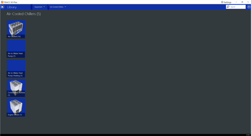
Air Cooled Chillers
Air cooled chillers are devices used to make cold water with an air cooled condenser. In this library, you can create different types of air cooled chillers:


Air Cooled
This chiller uses performance information at reference conditions along with three curve fits for cooling capacity and efficiency to determine the chiller operation at off-reference conditions.
 
 
Product tab
 
Nominal Cooling Capacity
Default: Auto Size
Typical Range: 50 to 500 tons
Min/Max: 0 < X < 999,999
Units: W; kW; tons; Btuh; Mbh
This field specifies the nominal cooling capacity of the chiller.
 
 
Full Load Energy Rate
Default: 0
Typical Range: 2.9 to 3.1 COP
Min/Max: 0 to 999,999
Units: kW/ton; therms/ton-hr; Mbh/ton; kW/Mbh; kW/kW; COP; EER
This numeric input field is the chiller’s coefficient of performance. It should not include energy use due to pumps. This value should include the air cooled condenser fans if the Condenser fan field below is not used.
 
 
Optimum Part Load Ratio
Default: 100%
Typical Range: 10 to 100%
Min/Max: 0 to 100%
Units: %
This numeric field contains the chiller’s optimum part-load ratio. This is the part-load ratio at which the chiller performs at its maximum COP.
 
 
Sizing Factor
Default: 100%
Typical Range: 10 to 100%
Min/Max: 0 to 999,999
Units: %
The sizing factor is used when the capacity is selected as auto sized. The autosizing calculations are performed as usual and the results are multiplied by the sizing factor.
 
 
Design Water Temperatures
Design Leaving Chilled Water Temperature
Default: 44°F (6.67°C)
Typical Range: 44 to 45°F (6.67 to 7.2°C)
Min/Max: 20°F (-7°C)
Units: °F (°C)
This field contains the chiller’s leaving chilled water temperature.
 
Design Entering Condenser Air Temperature
Default: 95°F (35°C)
Typical Range: 85 to 95°F (29.4 to 35°C)
Min/Max: 75 to 120°F (23.8 to 48.8°C)
Units: °F (°C)
This field contains the chiller’s entering condenser fluid temperature. It represents the entering outdoor air dry-bulb.
 
Compressor
Compressor Type
Default: N/A
Typical Range: N/A
Min/Max: N/A
Units: N/A
This field defines the chiller’s type of compressor. The available options are: Generic Screw, Helical Rotary, Reciprocating and Scroll.
 
Compressor Heat Rejection Fraction
Default: 100%
Typical Range: 0 < X< 100%
Min/Max: 0 < X < 100%
Units: %
This input represents the fraction of compressor electrical energy consumption that must be rejected by the condenser. Enter a value of 1.0 when modeling hermetic chillers. For open chillers, enter the compressor motor efficiency.
 
 
Operational Limits
Leaving Chilled Water Temperature Low Limit
Default: 35.6°F (2°C)
Typical Range: N/A
Min/Max: 10 to 60°F (12.2 to 15.6°C)
Units: °F (°C)
This field contains the lower limit for the leaving chilled water temperature. This temperature acts as a cut off for heat transfer in the evaporator, so that the fluid doesn’t get too cold.
 
Condenser Fan
Condenser Fan Power Capacity Ratio
Default: 0.89 COP
Typical Range: N/A
Min/Max: 0 to 999,999
Units: COP; kW/ton; kW/kW
This field is used to model condenser fan power associated with air-cooled condensers. Enter the ratio of the condenser fan power to the reference chiller cooling capacity. If this input is greater than 0, the condenser fan power is modeled separately from the compressor power. In addition, if the condenser fan power is modeled using this input, the Full Load Energy Rate field and the performance curves should not include the condenser fan power.
 
 
Basin Heater
Condenser Type
Default: Air-cooled
Typical Range: N/A
Min/Max: N/A
Units: N/A
This field determines what type of condenser will be modeled with this chiller. Valid condenser types are Air-Cooled and Evaporatively Cooled.
 
 
Curve tab
There are two sets of curves for Air Cooled Chillers depending on the operating mode of the chiller: Cooling Mode and Ice Storage. The description of the curves are below.
 
 
Capacity Curve
This biquadratic curve shows the percentage of full cooling capacity as a function of the entering condenser fluid temperature and the leaving chilled water temperature. Inputs consists of two independent variables, six coefficients, and min and max values for each of the independent variables. The equation for the capacity curve is:
Where:
Z = Cooling Capacity
C1 to C6 = coefficients
X = Condenser temperature
Y = Chilled Water Temperature
 
The curve has the following fields:
X Axis: Entering Condenser fluid temperature (°F, °C).
Y Axis: Cooling Capacity (%).
Tchw,l Min / Max : Minimum and maximum temperature values (°F, °C) for the Chilled water leaving temperature variable. These values determine the three chilled water temperatures plotted, one is the maximum, one is the minimum and the last one is the midpoint between them.
Tcond,l Min / Max: Minimum and Maximum temperature values (°F, °C) for the Condenser Temperature variable.
 
 
Ambient Relief Curve
This biquadratic curve represents the chiller’s energy input to cooling output ratio as a function of the entering condenser fluid temperature and the leaving chilled water temperature.
 
Inputs consists of two independent variables, six coefficients, and min and max values for each of the independent variables. The equation for the capacity curve is:
Where:
Z = Chiller’s electric consumption (%)
C1 to C6 = coefficients
X = Condenser temperature
Y = Chilled Water Temperature
 
The curve has the following fields:
X Axis: Entering Condenser fluid temperature (°F, °C).
Y Axis: Chiller’s electric consumption (%)
Tchw,l Min / Max : Minimum and maximum temperature values (°F, °C) for the Chilled water leaving temperature variable. These values determine the three chilled water temperatures plotted, one is the maximum, one is the minimum and the last one is the midpoint between them.
Tcond,l Min / Max: Minimum and Maximum temperature values (°F, °C) for the Condenser Temperature variable.


Power Curve (Electric Input to Cooling Output Ratio Function of Part Load Ratio Curve)
This quadratic curve represents the chiller’s electric consumption at part load with operating temperatures at design values. This curve is generated by dividing the operating electric input power by the available full-load capacity at the specific operating temperatures. The curve output should decrease from 1 towards 0 as part-load ratio decreases from 1 to 0.
The equation for the Fuel Capacity Curve is:
 
Where:
y = Chiller’s electric consumption (%)
C1 to C3 = coefficients
X = Part Load
 
The curve has the following fields:
X Axis: Full Load (%)
Y Axis: Full power (%)
Curve Type: The curve can be selected as quadratic or cubic.
Load Min / Max: Minimum and Maximum Load percentage
 
Air to Water Heat Pump
Please visit the Air to Water Heat Pump answer on our support portal. More detailed information will be added to the User Guide soon.
            
 
Combustion Turbine Chiller
The Combustion Turbine Chiller uses a combustion turbine to generate electrical output to run the chiller. It can burn different types of fuels to generate steam to move the turbine.


Product tab
 
Nominal Cooling Capacity
Default: Auto Size
Typical Range: 50 to 500 tons
Min/Max: 0 < X < 999,999
Units: W; kW; Btuh; Mbh
This field specifies the nominal cooling capacity of the chiller.
 
 
Full Load Energy Rate
Default: 0
Typical Range: 2.9 to 3.1 COP
Min/Max: 0 to 999,999
Units: kW/ton; therms/ton-hr; Mbh/ton; kW/Mbh; kW/kW; COP; EER
This field is the chiller’s coefficient of performance.
 
 
Temperature Rise Coefficient
Default: 2.778
Typical Range: 2.778
Min/Max: 0 to 999,999
Units: N/A
This field contains the electric chiller’s temperature rise coefficient which is defined as the ratio of the required change in condenser water temperature to a given change in chilled water temperature. This maintains the capacity at the nominal value and is calculated as the following ratio:
where:
TCEntrequired = required entering condenser air or water temperature to maintain rated capacity
TCEntrated = rated entering condenser air or water temperature at rated capacity
TELvrequired = required leaving evaporator water outlet temperature to maintain rated capacity
TELvrated = rated leaving evaporator water outlet temperature at rated capacity
 
 
Fuel Type
Default: Natural Gas
Typical Range: N/A
Min/Max: N/A
Units: N/A
This field determines the type of fuel that the chiller uses. Fuel options are: NaturalGas, PropaneGas, Diesel, Gasoline, FuelOil#1, FuelOil#2, OtherFuel1 or OtherFuel2.
 
 
Optimum Part Load Ratio
Default: 100%
Typical Range: 10 to 100%
Min/Max: 0 to 100%
Units: %
This numeric field contains the chiller’s optimum part-load ratio. This is the part-load ratio at which the chiller performs at its maximum COP.
 
 
Sizing Factor
Default: 100%
Typical Range: 10 to 100%
Min/Max: 0 to 100%
Units: %
The sizing factor is used when the capacity is selected as auto sized. The autosizing calculations are performed as usual and the results are multiplied by the sizing factor.
 
 
Design Fluid Temperatures
Design Entering Condenser Air Temperature
Default: 95°F (35°C)
Typical Range: 85 to 95°F (29.4 to 35°C)
Min/Max:  75 to 120°F (23.8 to 48.8°C)
Units: °F (°C)
This field contains the combustion turbine chiller’s condenser inlet design temperature.
 
 
Design Leaving Chilled Water Temperature
Default: 44.1°F (6.67°C)
Typical Range: 43 to 45°F (6.11 to 7.22°C)
Min/Max: -130 to 158°F (-90 to 70°C)
Units: °F (°C)
This field contains the combustion turbine chiller’s evaporator outlet design temperature.
 
 
Operational Limits
Leaving Chilled Water Temperature Low Limit
Default: 41°F (5°C)
Typical Range: 34 to 41°F (1.11 to 5°C)
Min/Max: -130 to 158°F (-90 to 70°C)
Units: °F (°C)
This numeric field contains the lower limit for the evaporator outlet temperature. This temperature acts as a cut off for heat transfer in the evaporator, so that the fluid doesn’t get too cold.
 
 
Gas Turbine
Nominal Engine Capacity
Default: Auto Size
Typical Range: Auto Size
Min/Max: 0 to 99,999,999 kW
Units: W; kW; tons; Btuh; Mbh
This field contains the capacity of the gas turbine engine.
 
Exhaust Flow per Engine Capacity
Default: 0.0000054 (kg/s)/W
Typical Range: Depends on chiller performance
Min/Max: 0 to 99,999,999 kW
Units: (lb/hr)/W; (kg/s)/W
This field contains the maximum exhaust gas mass flow rate per kilowatt of power out.
 
Design Steam Saturation Temperature
Default: 302°F (150°C)
Typical Range: Depends on chiller performance
Min/Max: 212 to 420°F (100 to 215°C)
Units: °F (°C)
This field contains the design steam saturation temperature.
 
Fuel Higher Heating Value
Default: 43,500 kJ/kg for Natural Gas
Typical Range: Depends on fuel type
Min/Max: 20267 to 22453 Btu/lb (47,130 to 52,210 kJ/kg)
Units: Btu/lb; kJ/kg; J/kg
Also known as the gross energy of a fuel or gross calorific value. This field contains the higher heating value of the fuel.
 
 
Basin Heater
Condenser Type
Default: Air-cooled
Typical Range: N/A
Min/Max: N/A
Units: N/A
This field determines what type of condenser will be modeled with this chiller. Valid condenser types are Air-Cooled and Evaporative Cooled.
 
 
Curve tab
The description of the performance curves for the Combustion Turbine Air cooled chillers is listed below.


Capacity Curve
This quadratic curve determines the ratio of available capacity to nominal capacity.
The equation for the Capacity Curve is:
Where:
y = Chiller’s available capacity to nominal capacity ratio (%)
C1 to C3 = coefficients
 
TempCondIn = Temperature entering the condenser (water or air temperature depending on condenser type)
TempCondInDesign = Temp Design Condenser Inlet from User input above
TempEvapOut = Temperature leaving the evaporator
TempEvapOutDesign = Temp Design Evaporator Outlet from User input above
TempRiseCoefficient = User Input from above
 
The curve has the following fields:
X Axis:
Y Axis: Full Capacity (%)
Curve Type: The curve is quadratic
Min / Max: Minimum and Maximum Delta T
 
 
Capacity –Power Curve (Power ratio curve)
This quadratic curve shows the percentage of full power capacity as a function of the chiller’s capacity. The equation for the Capacity-Power Curve is:
Where:
y = percentage of full power (%)
C1 to C3 = coefficients
X = percentage of full load capacity (%)
 
The curve has the following fields:
X Axis: Full capacity (%)
Y Axis: Full Power (%)
Curve Type: The curve is quadratic
Capacity Min / Max: Minimum and Maximum percentage of the capacity
 
Power Curve (Full Load Ratio)
This quadratic curve shows the fraction of full load power capacity as a function of the chiller’s Part load ratio. The equation for the Capacity-Power Curve is:
Where:
y = fraction of full power (%)
C1 to C3 = coefficients
X = part load ratio (%)
 
The curve has the following fields:
X Axis: Full load (%)
Y Axis: Full Power (%)
Curve Type: The curve is quadratic
Capacity Min / Max: Minimum and Maximum percentage of the load
 
 
Fuel used Curve (Fuel Input curve)
This quadratic curve determines the Ratio of Fuel Input to Energy Output. The equation for the Fuel used Curve is:
Where:
y = Ratio of Fuel Input to Energy Output (%)
C1 to C3 = coefficients
X = Ratio of Load to Combustion Turbine Engine Capacity (%)
 
The curve has the following fields:
X Axis: Full load to Capacity (%)
Y Axis: Fuel Use (%)
Curve Type: The curve is quadratic
Load to Capacity Min / Max: Minimum and Maximum percentage of the load to capacity
 
 
Fuel used - Temperature Curve
This quadratic curve determines the Ratio of Fuel Input to the Temperature Difference between the current and design ambient temperatures. The equation for the Fuel used Curve is:
Where:
y = Ratio of Fuel Input to (%)
C1 to C3 = coefficients
X = (Current Ambient Temperature – Design Ambient Temperature) (°F)
 
The curve has the following fields:
X Axis:  (°F)
Y Axis: Fuel Use (%)
Curve Type: The curve is quadratic
, Outdoor Min / Max: Minimum and Maximum Outdoor temperature difference


Engine Driven Chiller
The Engine Driven Chiller uses a fuel fired engine to drive the compressor. The fuel can be natural gas, propane gas, diesel or gasoline.
 
 
Product tab
Nominal Cooling Capacity
Default: Auto Size
Typical Range: 50 to 500 tons
Min/Max:  0 < X < 999,999
Units: W; kW; Btuh; Mbh
This field specifies the nominal cooling capacity of the chiller.
 
 
Full Load Energy Rate
Default: 0 COP
Typical Range: 2.9 to 3.1 COP
Min/Max:  0 to 999,999
Units: kW/ton, therms/ton-hr, Mbh/ton, kW/Mbh, kW/kW, COP, EER
This numeric input field is the chiller’s coefficient of performance.
 
 
Temperature Rise Coefficient
Default: 2.778
Typical Range: 2.778
Min/Max:  0 to 999,999
Units: N/A
This field contains the electric chiller’s temperature rise coefficient which is defined as the ratio of the required change in condenser water temperature to a given change in chilled water temperature, which maintains the capacity at the nominal value. This is calculated as the following ratio:
where:
TCEntrequired = required entering condenser air or water temperature to maintain rated capacity
TCEntrated = rated entering condenser air or water temperature at rated capacity
TELvrequired = required leaving evaporator water outlet temperature to maintain rated capacity
TELvrated = rated leaving evaporator water outlet temperature at rated capacity
 
 
Fuel Type
Default: Diesel
Typical Range: N/A
Min/Max:  N/A
Units: N/A
This field determines the type of fuel that the chiller uses. Fuel types are: NaturalGas, PropaneGas, Diesel, Gasoline, FuelOil#1, FuelOil#2, OtherFuel1 or OtherFuel2.
 
 
Sizing Factor
Default: 100%
Typical Range: 10 to 100%
Min/Max:  0 to 100%
Units: %
The sizing factor is used when the capacity is selected as auto sized. The autosizing calculations are performed as usual and the results are multiplied by the sizing factor.
 
 
Design Fluid Temperatures
Design Entering Condenser Air Temperature
Default: 95°F (35°C)
Typical Range: 85 to 95°F (29.4 to 35°C)
Min/Max: 75 to 120°F (23.8 to 48.8°C)
Units: °F (°C)
This field contains the combustion turbine chiller’s condenser inlet design temperature.
 
Design Leaving Chilled Water Temperature
Default: 44.1°F (6.67°C)
Typical Range: 43 to 45°F (6.11 to 7.22°C)
Min/Max: -130 to 158°F (-90 to 70°C)
Units: °F (°C)
This field contains the combustion turbine chiller’s evaporator outlet design temperature.
 
 
Operational Limits
Leaving Chilled Water Temperature Low Limit
Default: 41°F (5°C)
Typical Range: 34 to 41°F (1.11 to 5°C)
Min/Max: -130 to 158°F (-90 to 70°C)
Units: °F (°C)
This numeric field contains the lower limit for the evaporator outlet temperature. This temperature acts as a cut off for heat transfer in the evaporator, so that the fluid doesn’t get too cold.
 
 
Exhaust
Exhaust Flow per Engine Capacity
Default: 0.00063 (kg/s/W)
Typical Range: Depends on chiller performance
Min/Max: 0 to 99,999,999 kW
Units: (lb/hr)/W, (kg/s)/W
This field contains the maximum exhaust gas mass flow rate per kilowatt of cooling provided by the engine driven chiller.
 
Design Minimum Exhaust Temperature
Default: 302°F (150°C)
Typical Range: Depends on chiller performance
Min/Max: 212 to 420°F (100 to 215°C)
Units: °F (°C)
This field contains the design steam saturation temperature that would be used to determine the energy recovered from a water jacket heat exchanger on the engine.
 
Fuel Higher Heating Value
Default: 43,500 kJ/kg for Natural Gas
Typical Range: Depends of Fuel Type
Min/Max: 20267 to 22453 Btu/lb / 47,130 to 52,210 kJ/kg
Units: Btu/lb, kJ/kg, J/kg
Also known as the gross energy of a fuel or gross calorific value. This field contains the higher heating value of the fuel used.
 
 
Basin Heater
Condenser Type
Default: Air-cooled
Typical Range: N/A
Min/Max: N/A
Units: N/A
This field determines what type of condenser will be modeled with this chiller. Valid condenser types are Air-Cooled and Evaporative Cooled.
 
 
Curve tab
The description of the performance curves for the Engine Driven Air cooled chillers is listed below.
 
 
Capacity Ratio Curve
This quadratic curve determines the ratio of available capacity to nominal capacity.
The equation for the Capacity Curve is:
Where:
y = Chiller’s available capacity to nominal capacity ratio (%)
C1 to C3 = coefficients
 
TempCondIn = Temperature entering the condenser (water or air temperature depending on condenser type)
TempCondInDesign = Temp Design Condenser Inlet from User input above
TempEvapOut = Temperature leaving the evaporator
TempEvapOutDesign = Temp Design Evaporator Outlet from User input above
TempRiseCoefficient = User Input from above
 
The curve has the following fields:
X Axis:
Y Axis: Full Capacity (%)
Curve Type: The curve is quadratic
Min / Max: Minimum and Maximum Delta T


Capacity –Power Curve (Power ratio curve)
This quadratic curve shows the percentage of full power capacity as a function of the chiller’s capacity. The equation for the Capacity-Power Curve is:
Where:
y = percentage of full power (%)
C1 to C3 = coefficients
X = percentage of full load capacity (%)
 
The curve has the following fields:
X Axis: Full capacity (%)
Y Axis: Full Power (%)
Curve Type: The curve is quadratic
Capacity Min / Max: Minimum and Maximum percentage of the capacity
 
 
Power Curve (Full Load Ratio)
This quadratic curve shows the fraction of full load power capacity as a function of the chiller’s Part load ratio. The equation for the Capacity-Power Curve is:
Where:
y = fraction of full power (%)
C1 to C3 = coefficients
X = part load ratio (%)
 
The curve has the following fields:
X Axis: Full load (%)
Y Axis: Full Power (%)
Curve Type: The curve is quadratic
Capacity Min / Max: Minimum and Maximum percentage of the load


Fuel used Curve (Fuel Input curve)
This quadratic curve determines the Ratio of Fuel Input to Cooling Part Load. The equation for the Fuel used Curve is:
Where:
y = Ratio of Fuel Input to Cooling Load Output (%)
C1 to C3 = coefficients
X = Full Load (%)
 
The curve has the following fields:
X Axis: Part Load (%)
Y Axis: Fuel Use (%)
Curve Type: The curve is quadratic
Full Load Min / Max: Minimum and Maximum percentage of the load to capacity