Trace 3D Plus
User Guide
 
×


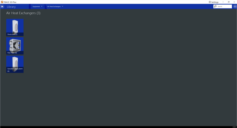
Air Heat Exchangers
Air heat exchangers are devices used to transfer heat between fluids. There are three types of air to air heat exchangers in this library:


Desiccant
The Desiccant heat exchanger is an HVAC component that models temperature (sensible) and moisture (latent) heat exchange between two airstreams. This air–to-air heat exchanger preconditions the air entering the cooling coil by removing moisture from the air through its desiccant material. The air flow rates as well as the velocities are considered balanced (same for both regeneration and process air streams).


Product tab
 
Design Face Velocity
Default: Auto Size
Typical Range: Auto Size
Min Max: 0 < X < 19.68 ft/s (6 m/s)
Units: m3/s; cfm
This field specifies the nominal air velocity across the heat exchanger face area. Since it is balanced, it will have the same rate for both sides of the heat exchanger regeneration and process.
 
 
Full Load Power
Default: 0
Typical Range: 120 to 372 W
Min Max: 0 to 999,999
Units: W; hp; kW
This numeric input field is the nominal electric consumption rate of the heat exchanger while it operates. It represents the full load power of the motor or controls that rotates the wheel. The power is considered a constant value and does not contribute to the thermal load of either air streams.
 
 
Economizer Lockout
Default: Yes
Typical Range: No
Min Max: Yes
Units: N/A
This input denotes whether the heat exchanger unit is locked out (heat exchanger rotation is suspended) when the air-side economizer is operating. The input choices are Yes (meaning locked out) or No.


Curve tab
 
Regeneration Dry Bulb Curve
This polynomial curve reflects the regeneration air stream outlet temperature as a function of the entering regeneration and process air stream temperature, humidity ratio and face velocity.
 
The dry-bulb temperature of the regeneration outlet air is determined using the equation:
Where
RTO = regeneration outlet air dry bulb temperature (°F, °C)
RWI= regeneration inlet air humidity ratio (kgWater/kgDryAir)
RTI = regeneration inlet air dry bulb temperature (°F, °C)
PWI = process inlet air humidity ratio (kgWater/kgDryAir)
PTI = process inlet air dry bulb temperature (°F, °C)
RFV = Regeneration (and process) face velocity (m/s)
B1 to B8 = coefficients
The curve has the following fields:
X Axis: Regeneration inlet air dry bulb temperature (°F, °C)
Y Axis: Regeneration outlet air dry bulb temperature (°F, °C)
Treg,db Min / Max : Minimum and maximum temperature values (°F, °C) for the regeneration inlet air dry bulb temperature
Tproc,db Min / Max: Minimum and maximum temperature values (°F, °C) for the process inlet air dry bulb temperature
Proc. Inlet Air HR Min / Max: Minimum and maximum Humidity Ratio values (kgWater/kgDryAir) for the process inlet air humidity ratio
Reg. Inlet Air HR Min / Max: Minimum and maximum Humidity Ratio values (kgWater/kgDryAir) for the regeneration inlet air humidity ratio
Velocity Min / Max: Minimum and maximum face velocity (m/s)


Regeneration Humidity Ratio Curve
This polynomial curve reflects the regeneration air stream outlet humidity ratio as a function of the entering regeneration and process air stream temperature, humidity ratio and face velocity.
 
The dry-bulb temperature of the regeneration outlet air is determined using the equation:
Where
RWO = regeneration outlet air humidity ratio (kgWater/kgDryAir)
RWI= regeneration inlet air humidity ratio (kgWater/kgDryAir)
RTI = regeneration inlet air dry bulb temperature (°F, °C)
PWI = process inlet air humidity ratio (kgWater/kgDryAir)
PTI = process inlet air dry bulb temperature (°F, °C)
RFV = Regeneration (and process) face velocity (m/s)
C1 to C8 = coefficients
 
The curve has the following fields:
X Axis: Regeneration inlet air humidity ratio (kgWater/kgDryAir)
Y Axis: Regeneration outlet air humidity ratio (kgWater/kgDryAir)
Treg,db Min / Max : Minimum and maximum temperature values (°F, °C) for the regeneration inlet air dry bulb temperature
Tproc,db Min / Max: Minimum and maximum temperature values (°F, °C) for the process inlet air dry bulb temperature
Proc. Inlet Air HR Min / Max: Minimum and maximum Humidity Ratio values (lbWater/lbDryAir,   kgWater/kgDryAir) for the process inlet air humidity ratio
Reg. Inlet Air HR Min / Max: Minimum and maximum Humidity Ratio values (lbWater/lbDryAir,   kgWater/kgDryAir) for the regeneration inlet air humidity ratio
Velocity Min / Max: Minimum and maximum face velocity (ft/min, m/s)


Flat Plate
The Flat Plate heat exchanger is an HVAC component where two airstreams cross by each other. It is used to precondition Outside Air by transferring sensible heat with the return air. There are three types of arrangements: counter flow, parallel flow or cross flow. There is no need to enter dimensions since the performance is determined by specifying the design inlet and outlet temperatures, the convection ratio and if it is operating with an economizer and economizer operation. 


Product tab


Heat Exchanger Type
Default: Counter-flow Both Unmixed
Typical Range: N/A
Min Max: N/A
Units: N/A
There are three types of flow configurations: counter-flow, parallel flow or cross-flow both unmixed.
 
 
Parasitic Energy
Default: 0 W
Typical Range: 0 to 0.4 kW
Min Max: -999,999 to 999,999
Units: W; kW; hp
This field represents the electric power consumed by the controls or motor of the rotary heat exchanger. The electric power is considered constant when the unit is operating and it doesn’t contribute to the thermal load of any of the air streams.


Design Inlet Exhaust Air Temperature
Default: 75°F (23.9°C)
Typical Range: 60 to 120°F (15 to 48°C)
Min Max: -130 to 158°F (-90 to 70°C)
Units: °F; °C
This is the temperature of the exhaust airflow that goes into the heat exchanger.
 
 
Design Outlet Air Temperature
Default: 80°F (26.7°C)
Typical Range: 60 to 120°F (15 to 48°C)
Min Max: -130 to 158°F (-90 to 70°C)
Units: °F; °C
This is the temperature of the main supply airflow when leaving the Heat exchanger.
 
 
Design Inlet Air Temperature
Default: 95°F (35°C)
Typical Range: 60 to 120°F (15 to 48°C)
Min Max: -130 to 158°F (-90 to 70°C)
Units: °F; °C
This is the temperature of the main supply airflow when entering the Heat exchanger.
 
 
Convection Ratio
Default: 1
Typical Range: 1
Min Max: 0 to 1
Units: N/A
This value is the heat transfer ratio between the supply and exhaust air sides.  
It is defined as:
Where
h = surface convective heat transfer coefficient
A = heat transfer area
S = supply airside
Ex = exhaust airside
 
 
Economizer Lockout
Default: Yes
Typical Range: Yes
Min Max: No, Yes
Units: N/A
This input denotes whether the heat exchanger unit is locked out (bypassed) when the air side economizer is operating. The input choices are Yes (meaning locked out) or No.


Sensible and Latent
The sensible and latent air to air heat exchanger is an HVAC component for exhaust heat recovery. It can be used to transfer sensible energy, latent energy or both between the supply and exhaust air streams. The performance is specified by its sensible or latent effectiveness at 75% and 100% of the nominal supply air flow rate at two operating conditions (consistent with ARI Standard 1060-2001) as shown in the following table.
 
Table 1. Operating conditions for Sensible and Latent Heat Exchanger
Parameter
Conditions
 
Heating
Cooling
Entering supply air temperature:
Dry Bulb
35°F (1.7°C)
95°F (35°C)
Wet Bulb
33°F (0.6°C)
78°F (26°C)
Entering exhaust air temperature:
Dry Bulb
70°F (21°C)
75°F (24°C)
Wet Bulb
58°F (14°C)
63°F (17°C)


Product tab


Heat Exchanger Type
Default: Plate
Typical Range: N/A
Min Max: Rotary, Plate
Units: N/A
There are two types of sensible and latent heat exchanger: Plate, like a fixed plate and Rotary, like a rotary cylinder or wheel. The type of heat exchanger determines the frost control options to prevent frost formation and to control the supply air outlet temperature. For Plate, the air is bypassed around the heat exchanger, for Rotary, the rotational speed is varied.
 
 
Parasitic Energy
Default: 0 W
Typical Range: 0 to 0.4 kW
Min Max: -999,999 to 999,999
Units: W, kW, hp
This field represents the electric power consumed by the controls or motor of the rotary heat exchanger. The electric power is considered constant when the unit is operating and it doesn’t contribute to the thermal load of any of the air streams.
 
 
Economizer Lockout
Default: Yes
Typical Range: Yes
Min Max: Yes and No
Units: N/A
This input denotes whether the heat exchanger unit is locked out (bypassed for plate or if the rotation is suspended for rotary type) when the air side economizer is operating. The input choices are Yes (meaning locked out) or No.
 
 
Sensible
 
Cooling Effectiveness at 100% Airflow
Default: 33
Typical Range: 0 to 100
Min Max: 0 to 100
Units: %
This field is the sensible heat exchange effectiveness at the cooling condition defined in Table1 with both the supply and exhaust air volume flow rates equal to 100% of the supply air flow rate calculated.
 
Cooling Effectiveness at 75% Airflow
Default: 37
Typical Range: 0 to 100
Min Max: 0 to 100
Units: %
This field is the sensible heat exchange effectiveness at the cooling condition defined in Table1 with both the supply and exhaust air volume flow rates equal to 75% of the supply air flow rate calculated.
 
Heating Effectiveness at 100% Airflow
Default: 33
Typical Range: 0 to 100
Min Max: 0 to 100
Units: %
This field is the sensible heat exchange effectiveness at the heating condition defined in Table1 with both the supply and exhaust air volume flow rates equal to 100% of the supply air flow rate calculated.
 
Heating Effectiveness at 75% Airflow
Default: 37
Typical Range: 0 to 100
Min Max: 0 to 100
Units: %
This field is the sensible heat exchange effectiveness at the heating condition defined in Table1 with both the supply and exhaust air volume flow rates equal to 75% of the supply air flow rate calculated.
 
 
Latent
 
Cooling Effectiveness at 100% Airflow
Default: 0
Typical Range: 0 to 100
Min Max: 0 to 100
Units: %
This field is the latent heat exchange effectiveness at the cooling condition defined in Table1 with both the supply and exhaust air volume flow rates equal to 100% of the supply air flow rate calculated.
 
Cooling Effectiveness at 75% Airflow
Default: 0
Typical Range: 0 to 100
Min Max: 0 to 100
Units: %
This field is the latent heat exchange effectiveness at the cooling condition defined in Table1 with both the supply and exhaust air volume flow rates equal to 75% of the supply air flow rate calculated.
 
Heating Effectiveness at 100% Airflow
Default: 0
Typical Range: 0 to 100
Min Max: 0 to 100
Units: %
This field is the latent heat exchange effectiveness at the heating condition defined in Table1 with both the supply and exhaust air volume flow rates equal to 100% of the supply air flow rate calculated. If the heat exchanger does not transfer latent energy, specify this value as zero.
 
Heating Effectiveness at 75% Airflow
Default: 0
Typical Range: 0 to 100
Min Max: 0 to 100
Units: %
This field is the latent heat exchange effectiveness at the heating condition defined in Table1 with both the supply and exhaust air volume flow rates equal to 75% of the supply air flow rate calculated. If the heat exchanger does not transfer latent energy, specify this value as zero.


Frost Control
 
Frost Control type
Default: None
Typical Range: N/A
Min Max: N/A
Units: N/A
There are four options for this control: None, Exhaust Air Recirculation, Exhaust Only and Minimum Exhaust Temperature.
None: For modeling preheat frost control, specify none for this input field and insert a separate heating coil object in the supply inlet air stream to keep the air temperature above the desired frost threshold temperature.
 
Minimum Exhaust Temperature: the temperature of the exhaust air leaving the heat exchanger is monitored and the heat exchanger effectiveness is decreased (by slowing heat exchanger rotation or bypassing supply air around the plate exchanger) to keep the exhaust air from falling below the threshold temperature.
 
Exhaust Only (supply air bypass): this control cycles off the supply air flow through the heat exchanger for a certain period of time while the exhaust air continues to flow through the exhaust side of the heat exchanger. The fraction of time that the supply flow through the heat exchanger is cycled off is dependent on the supply (outdoor) air inlet temperature with respect to the threshold temperature, the initial defrost time fraction, and the rate of change of defrost time fraction. For this frost control type, it is assumed that the supply air is bypassed around the heat exchanger during frost control operation.
 
Exhaust Air Recirculation: dampers are used to direct exhaust air back into the zone through the supply side of the heat exchanger when the supply (outdoor) air inlet temperature falls below a threshold temperature (defined in the next input field).  The fraction of time that exhaust air is circulated through the supply side of the heat exchanger depends on the supply (outdoor) air inlet temperature with respect to the threshold temperature, the initial defrost time fraction, and the rate of change of defrost time fraction. When exhaust air is being recirculated, no supply (outdoor ventilation) air is being provided through the heat exchanger unit.


Table 2. Typical threshold temperatures for Frost Control
Frost Control Type
Heat Exchanger Type
Energy Exchange
Threshold Temperature
Exhaust Air Recirculation
Plate
Sensible-only
30°F (-1.1°C)
Exhaust Air Recirculation
Plate
Plate Sensible + latent
10°F (-12.2°C)
Exhaust Air Recirculation
Rotary
Rotary Sensible-only
10°F (-12.2°C)
Exhaust Air Recirculation
Rotary
Rotary Sensible + latent
-10°F (-23.3°C)
Exhaust Only
Plate
Sensible-only
30°F (-1.1°C)
Exhaust Only
Plate
Sensible + latent
10°F (-12.2°C)
Exhaust Only
Rotary
Sensible-only
10°F (-12.2°C)
Exhaust Only
Rotary
Sensible + latent
-10°F (-23.3°C)
Minimum Exhaust Temperature
Plate
Sensible-only
35°F (-1.7°C)
Minimum Exhaust Temperature
Plate
Sensible + latent
35°F (-1.7°C)
Minimum Exhaust Temperature
Rotary
Sensible-only
35°F (-1.7°C)
Minimum Exhaust Temperature
Rotary
Sensible + latent
35°F (-1.7°C)
 
 
Threshold Temperature
Default: 35°F (1.7°C)
Typical Range: N/A
Min Max: N/A
Units: N/A
This numeric field is available only for the Minimum Exhaust Temperature control type is selected. It defines the dry-bulb temperature of air which is used to initiate frost control. The appropriate threshold temperature varies with exhaust (inlet) air temperature and humidity, frost control type, heat exchanger type, and whether the heat exchanger transfers sensible energy alone or both sensible and latent energy (enthalpy). Typical threshold temperatures are provided in Table2. However, it is recommended to consult the manufacturer’s information for the specific air-to-air heat exchanger that is modeled.


Defrost Time Fraction
Default: 0
Typical Range: 0 to 1
Min Max: 0 to 1
Units: N/A
This field is available for Exhaust Air Recirculation or Exhaust Only control types are selected. It defines the fraction of the simulation time step when frost control will be invoked when the threshold temperature is reached. This field is only used for the Exhaust Air Recirculation and Exhaust Only frost control types.
 
Typical value for Exhaust Air Recirculation frost control is 0.083 (5 min / 60 min)
Higher initial defrost time fractions are typically required for Exhaust Only frost control (e.g., 0.167 = 10 min / 60 min). For best results, obtain this information from the manufacturer.
 
Rate of Defrost Time Fraction
Default: 0.08
Typical Range: 0 to 1
Min Max: 0 to 999,999
Units: 1/°F; 1/°C; 1/°R; 1/K
This field defines the rate of increase in the defrost time fraction as the supply (outdoor) air inlet temperature falls below the threshold temperature. This field is only used for the
Exhaust Air Recirculation and Exhaust Only frost control types.
 
Typical value for Exhaust Air Recirculation frost control is 0.012 (0.72 min / 60 min per degree C temperature difference)
Higher values are typically required for Exhaust Only frost control (e.g., 0.024 = 1.44 min / 60 min per degree C temperature difference). For best results, obtain this information from the manufacturer.