Airflow
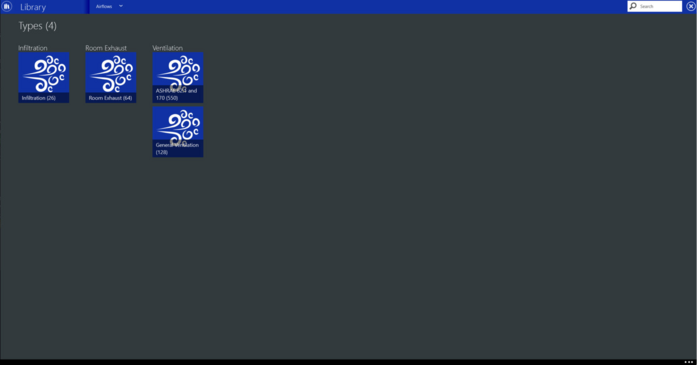
The airflows library category will allow you to create and manage airflow types that will be applied to zones in the creation of a building. They simulate the heat and moisture gains and losses from air. There are three types of airflow loads:


Click here for more information on General Library Navigation.


Infiltration
 
Infiltration is the unintended flow of air from the outdoor environment directly into a thermal zone. Infiltration is generally caused by the opening and closing of exterior doors, cracks around windows, and even in very small amounts through building elements.
 
The basic equation used by EnergyPlus™ to calculate infiltration is:
 
Infiltration = (Idesign)(Fschedule) [A + B| Tzone− Todb | + C WindSpeed + D Windspeed2]
 
Where
A = constant term coefficient
B = Temperature term coefficient
C= Velocity term coefficient
D = Velocity squared term coefficient
 
The default coefficients (A=1; B, C and D = 0) create a constant airflow infiltration.
 
These library members are applied to the building’s zones in the room properties screen. TRACE® 3D Plus has standard library members that include typical infiltration rates.
 
The infiltration library member details screen displays the fields that must be defined:
Name
Defines the name of the library member. Standard library members can’t be modified.
 
Airflow rate
Defines the infiltration rate that will be applied to a given zone. The rate can be defined as a rate per area of floor (cfm/sq. ft. floor), wall (cfm/sq. ft. wall), and air changes per hour or by the full design volume (cfm).
Default Value:  0.6 ACH
Typical Range: 0 to 1
Min & Max: 0 to 1,000,000
Units: cfm/ft2 floor, cfm/ft2 wall, cfm/ft2 surface, cfm, ACH ; (m3/s)/m2 floor, (m3/s)/m2 wall, (m3/s)/m2 surface, m3/s


Ventilation
 
Ventilation is outdoor air brought into the building mechanically to meet IAQ requirements. They are applied to the zones in the room properties screen. TRACE 3D Plus has standard library members that include ventilation rate requirements from several sources. There are two categories for ventilation: ASHRAE 62.1 and 170 (550) and General Ventilation.  Library members are available from multiple different release years of the standards.  Each member will specify where it came from under the Source Field.  
 
ASHRAE 62.1 and 170 (550)
The ventilation library members under this category will be used along with Zone Properties and System Sizing Inputs to calculate ventilation rates per ASHRAE Standard 62.1. In this category, the ventilation library member details screen displays the following fields that must be defined: 
 
People Based Rate
The design outdoor air volume flow rate per person for this zone in cubic meters per second per person. The default rates are from table 6-1 of ASHRAE Standard 62.1.
Default Value: Per ASHRAE 62.1- 2010 table 6-1 depending on the Occupancy Category
Typical Range: 5 to 20 cfm/ person
Min & Max: 0 to 1,000,000
Units: cfm/person; (L/s)/person, (m3/hr)/person, (m3/s)/person 
 
 
Area Based Rate
The design outdoor air volume flow rate per floor area. The default rates are from table 6-1 of ASHRAE Standard 62.1.  
Default Value: Per ASHRAE 62.1- 2010 table 6-1 depending on the Occupancy Category
Typical Range: 0.06 to 0.18 cfm/ ft2
Min & Max: 0 to 1,000,000
Units: cfm/ft2 ; (L/s)/m2, (m3/hr)/m2, (m3/s)/m2,  ACH (Air Changes an hour)
 
 
The following fields are part of the ASHRAE 62.1 calculations. They are defined in the Building & Site section, Create Zones subsection, for each zone. 
 
Cooling and Heating Ez
The Zone air distribution effectiveness is a measure of how thoroughly the cooling supply airflow mixes with the air in the breathing zone (the air up to six feet above the floor). This effectiveness is based on the location of the supply and return air grilles, the velocity of the airflow, and the proximity of the makeup air grille to the exhaust air grille. The available values are from table 6-2 of ASHRAE Standard 62.1- 2010 depending on the type of air distribution for the room.
Default Value: Per ASHRAE 62.1- 2010 table 6-2 depending on the Air Distribution Configuration
Typical Range: 0.5 to 1.2
Min & Max: N/A
Units: N/A
 
 
Er
The recirculation effectiveness is used only when the air handling system has a secondary ventilation path, such as a fan-powered VAV or dual duct VAV system. These systems can draw air from the plenum, and this field gives credit for the unused outside air in the plenum airstream. This input defines the local recirculation air fraction for the system return air.
Default Value: 0
Typical Range: 0.1 to 1.2
Min & Max: 0 to 100
Units: N/A
 
Select the type of recirculation for this room from the drop-down list and the corresponding effectiveness will automatically be displayed. If the specific Er for the room is known, this percentage can be entered manually by choosing Custom. The types of recirculation are listed in the table below. The percentage of effectiveness can only be modified if Custom is chosen. 
 
Type
Percentage
Custom
User entered
Default based on system type
blank
Recirculate from ceiling plenum (for example, fan-powered VAV)
30
Recirculate within room
0
RA is fully mixed before recirculation (for example, dual duct VAV)
100
Same vent quality as zone
0


General Ventilation
The standard library members under this category contain Infiltration, Room Exhaust, and Ventilation rates.  obtained from two sources: ASHRAE Standard 62.1- 2007, 2010, and 2013. In this category, the ventilation library member details screen displays the following fields that must be defined: 
 
Name
Defines the name of the library member. Standard library members can’t be modified.
 
      Flow Rate
The design outdoor air volume flow rate. The rate can be defined as a rate per area (cfm/sqft.), per person (cfm/person), air changes per hour or by the full design volume (cfm).
 
Default Value: Per ASHRAE 62.1-2013 table 2 depending on the Application
Typical Range: 15 to 60 cfm/person
Min & Max: 0 to 100,000
Units: cfm, cfm/ft2 , cfm/person, ACH; (m3/s)/person, (m3/s)/m2,    m3/s, L/s


Room Exhaust
 
Zone exhaust is zone air that is directly exhausted from the room to the atmosphere. These library members are applied to the building’s zones in the room properties screen. TRACE 3D Plus has standard library members that include typical zone exhaust rates from ASHRAE Standard 62.1-2013 Table 6.5. The room exhaust library member details screen displays the fields that must be defined: 
Name
Defines the name of the library member. Standard library members can’t be modified.
 
Airflow rate
Defines the exhaust rate that will be applied to a given zone. The rate can be defined as a rate per area of floor (cfm/sq. ft. floor), wall (cfm/sq. ft. wall), and air changes per hour or by the full design volume (cfm).
Default Value: Per ASHRAE 62.1-2013 table 6.5 depending on Occupancy category
Typical Range: 0.25 to 1.5 cfm; 2.5 to 5 m3/s
Min & Max: 0 to 1,000,000
Units: cfm, cfm/ft2 floor, cfm/ft2 wall, cfm/ft2 surface, cfm, ACH; m3/s, (m3/s)/m2 floor, (m3/s)/m2 wall, (m3/s)/m2 surface, m3/s


*See the Reference page for resources used in the help documentation.