Checksums
System Checksums
There are two “checksums” reports, the System Cooling Checksums and the System Heating Checksums. For sizing equipment, see the System Component Summary.
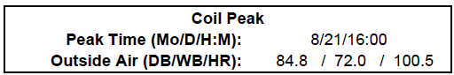
The two largest sections of this report are the Coil Peak and Fan Peak sections. The Coil Peak section shows all loads on the coil at the time of system coil peak. The time of system peak as well as the outdoor air conditions at that time are reported at the top. Dry bulb and wet bulb temperatures are reported in degrees F in IP and degrees C in SI. The humidity ratio is reported in grains/lb in IP and kg water/kg air in SI.
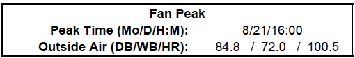
The Fan Peak section shows all sensible loads that are used for sizing the fan. If the fan is sized based on block, the loads will be summed for each of the zones at the time of system fan peak. If the fan is sized based on peak, the loads will be summed for each of the zones at each individual zone peak time.
Coil Peak section
At the top of the coil peak section, the user can find the peak time and corresponding outdoor air condition. In the example below, the coil peak occurred on August 21 at 16:00 (4:00 pm), with a corresponding outdoor air condition of 84.8 °F dry bulb, 72.0 °F wet bulb, and 100.5 gr/lb.
Below this is a table that breaks out the various loads simultaneous to the coil peak. The definition of each category is in the Component Definitions section below.
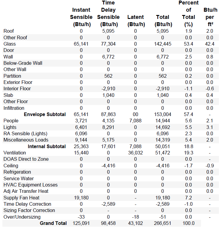
The table contains six columns:
|
Instant Sensible:
|
|
This is the sensible load to the space at the time of peak.This is a load that enters the space or is generated in the space at the peak hour.
|
|
Time Delay Sensible:
|
|
This is the sensible load due to radiant components of the load. The radiant components of internal loads are defined in the internal load libraries and in the internal load templates. There are also radiant components of envelope loads. These radiant loads are absorbed by the surfaces in the space and retransmitted at later hours. The time delay sensible load is an estimate of the current hour’s load and previous hours’ loads that are impacting the space at the time of peak. For more details on these calculations, see the Energy Plus Engineering Reference Manual in section 24.2 Component Loads Summary.
|
|
Latent:
|
|
This is the latent component of the load that impacts the space at the time of peak. The latent component of internal loads are defined in the internal loads library and can be edited in the internal load template in the project.
|
|
Total:
|
|
This is simply the sum of the instant sensible, time delay sensible, and latent loads.
|
|
Percent of Total:
|
|
This is calculated by (Percent of Total) = (Total)/(Grand Total)*100
|
|
Btu/h per ft2 (or W/m2):
|
|
This is a ratio of the total load and the area of the related surface. The surfaces used for each load component are listed in the table below. The area for each of these surfaces can be found in the Areas section of the report as well as the Related Area column of the Fan Peak section.
|
Fan Peak section
At the top of the fan peak section, the user can find the peak time and corresponding outdoor air condition. In the example below, the coil peak occurred on August 21 at 16:00 (4:00 pm), with a corresponding outdoor air condition of 84.8 °F dry bulb, 72.0 °F wet bulb, and 100.5 gr/lb.
Below this is a table that breaks out the various loads simultaneous to the coil peak. The definition of each category is in the Component Definitions section below.
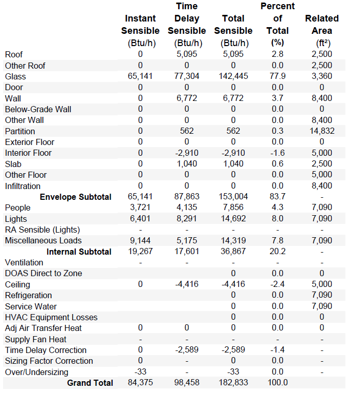
The table has five columns:
|
Instant Sensible:
|
|
This is the same as the Coil Peak section except at the time of fan peak rather than at the time of coil peak. If the coil and fan peak at the same time, these values will be the same.
|
|
Time Delay Sensible:
|
|
This is the same as the Coil Peak section except at the time of fan peak rather than at the time of coil peak. If the coil and fan peak at the same time, these values will be the same.
|
|
Total Sensible:
|
|
This is the sum of the instant sensible and the time delay sensible.
|
|
Percent of Total:
|
|
This is calculated by (Percent of Total) = (Total Sensible)/(Grand Total)*100
|
|
Related Area:
|
|
This is the area used in the Btuh per ft2 (W/m2) column in the Coil Peak section. This area relates to the particular load component. The area used for each component can be found in the table below. Keep in mind, if a surface doesn't directly impact the load in the space, it will not be included in the areas. For example, if all spaces on a particular system have a ceiling plenum, the roof won't directly impact the space and the roof area will report as 0.
|
Component Definitions
|
Component
|
Definition
|
Related Area
|
|
Envelope Loads
|
|
|
|
Roof
|
Roof surface defined in Create Building
|
Roof
|
|
Other Roof
|
not yet supported
|
Other Roof
|
|
Glass
|
Windows, skylights, and glass doors defined in Create Building.
|
Window
|
|
Door
|
Opaque doors defined in Create Building (Glass doors are in the glass category)
|
Door
|
|
Wall
|
Exterior walls defined in Create Building for above ground levels
|
Wall
|
|
Below-Grade Wall
|
Exterior walls defined in Create Building for basement levels
|
Below-Grade Wall
|
|
Other Wall
|
not yet supported
|
Other Wall
|
|
Partition
|
Interior walls defined in Create Building
|
Partition
|
|
Exterior Floor
|
Floor exposed to outside air (such as a cantilevered space)
|
Exterior Floor
|
|
Interior Floor
|
Floors between rooms on different levels
|
Internal Floor
|
|
Slab
|
Ground contact slab
|
Slab
|
|
Other Floor
|
not yet supported
|
Other Floor
|
|
Infiltration
|
Unconditioned outdoor air defined in the Airflows properties in Create Building
|
*
|
|
Internal Loads
|
|
|
|
People
|
People defined in the Internal Loads properties in Create Building
|
*
|
|
Lights
|
Portion of the lighting load to the space defined in the Internal Loads properties in Create Building
|
*
|
|
RA Sensible (Lights)
|
Portion of the lighting load to the return air defined in the Internal Loads properties in Create Building (see calculation method below)
|
*
|
|
Miscellaneous Loads
|
Miscellaneous loads defined in the Internal Loads properties in Create Building
|
*
|
|
Other Loads
|
|
|
|
Ventilation
|
See calculation method below
|
n/a
|
|
DOAS Direct to Zone
|
Load due to a Zone DOAS defined on the Select Systems tab. This is a DOAS that serves a zone directly. The System Level DOAS selected on the Configure Systems tab will not impact this output since the conditioned outdoor air is delivered to the main system coils and not directly to the zone. This type of DOAS will affect the ventilation component on this report instead. Both the zone level DOAS and the multi system DOAS will not impact this report because these serve only zone level systems and zone level systems are not reported on the System Checksums.
|
n/a
|
|
Ceiling
|
Ceiling load due to either a drop ceiling between a space and the plenum above, or a ceiling between a space and the space on the level above when there is no drop ceiling or plenum
|
Ceiling
|
|
Refrigeration
|
not yet supported
|
*
|
|
Service Water
|
not yet supported
|
*
|
|
HVAC Equipment Losses
|
not yet supported
|
n/a
|
|
Adj Air Transfer Heat
|
Load due to adjacent air being transferred between zones or systems.
|
|
|
Supply Fan Heat
|
Motor heat pickup from the supply fan defined by the motor heat to air field in the fan library and the fan full load energy rate defined in the fan library and system component properties
|
n/a
|
|
Time Delay Correction
|
This accounts for the difference between the exactly calculated sensible load and the sum of the estimated sensible components from this report. For more information, see note in the calculations section below.
|
n/a
|
|
Sizing Factor Correction
|
This accounts for the sizing factor applied in the Load Design Parameters tab of Simulation Settings (see calculation method below)
|
n/a
|
|
Airflow Correction
|
|
n/a
|
*Total area of all rooms on the system (found in the engineering checks section of the loads by component reports)
Calculations
RA sensible (lights)
Sensible Load = Return air component of lighting load - RA exhaust
Return Air Heat Exhausted: RA exhaust = (%OA/100) * coil flow * Cpmoistair * (return air dry bulb – room dry bulb)
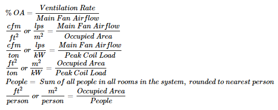
Ventilation calculation
Calculated using the sensible heat equation and the total load from the Fan Peak section.
Where:
ρ is the air density (Design Psychrometrics report).
Cp is the moist air heat capacity (Design Psychrometrics report).
ΔT is the difference between the outdoor dry bulb and the room dry bulb at ideal loads peak. In cooling, the room dry bulb is subtracted from the outdoor dry bulb. In heating, the outdoor dry bulb is subtracted from the room dry bulb. The outdoor dry bulb is shown as the Coil Peak Dry Bulb temperature. The room dry bulb is defined in the zone properties in the Create Zones tab.
Latent Load
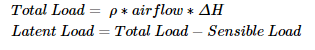
Where:
ρ is the air density (Design Psychrometrics report).
ΔH is the difference between the outdoor enthalpy and the room enthalpy at ideal loads peak. In cooling, the room enthalpy is subtracted from the outdoor enthalpy. In heating, the outdoor enthalpy is subtracted from the room enthalpy. The outdoor enthalpy is from the outdoor air drybulb at ideal loads peak and the outdoor air humidity ratio at ideal loads peak (Coil Peak Dry Bulb temperature and humidity ratio from Checksums report). The room enthalpy is from the zone air dry bulb at ideal loads peak and zone air humidity ratio at ideal loads peak (Coil Peak Dry Bulb temperature and humidity ratio from Checksums report)
Sizing Factor Correction
Heating
Sizing Factor = (Grand Total in the Total column)/(Grand Total in the Total column – Sizing Factor correction)
Cooling
Sizing Factor = (Instant Sensible + Time Delay Sensible – RA Sensible (Lights))/[ (Instant Sensible + Time Delay Sensible – RA Sensible (Lights)) – Sizing Factor Correction]
Again, the sizing factor is defined on the Load Design Parameters tab of the Simulation Settings.
Time Delay Correction
During the calculation, the program goes through a zone heat balance for each zone for each time step. These calculations determine each component of each load in the zone. Technically these load component values could be used to populate this report however this is too much data to store during the calculation. After each time step calculation, only the zone load is stored. These zone loads are used to determine the peak zone load and peak time. So when this report is populated, those load components are no longer known and are therefore estimated at the peak hour. This time delay correction represents the difference between the actual calculated load and the sum of the estimated loads from this report.
Temperatures
The temperatures section on the right of the screen shows the supply dry bulb, return dry bulb, mixed air dry bulb, and fan heat temperature difference (TD). In the example below, the fan added 2.1 °F to the supply air.
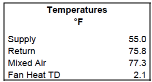
Supply
This is the main supply temperature entered in the system sizing properties. Keep in mind that this is the system level supply air temperature which is not necessarily the supply air temperature to the space. For example, the VAV RH (30% Min Default) (DX) system has a main heating and cooling coil as well as a zone level terminal box reheat coil. The system is designed so the main heating coil preheats the air to 55 F and the reheat coil heats it the rest of the way to 90 F. Because the reheat coil is zone level, it is not considered in this report, the main heating supply temperature is reported as 55 F because this is the leaving preheat coil temperature.
Return
This is the return air temperature from the space calculated by the program
Mixed Air
This is the mixed air temperature calculated using the mixed air equation for the return air, outdoor air, and percent outdoor air:
The %OA used in this calculation may not be the same as the %OA reported in the Airflows section of this report if the coil and the fan do not peak at the same time
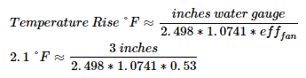
Fan Heat Temperature Difference
In the example above, the fan heat may be approximated in the IP form, using an Air Density Specific Heat Factor of 1.0741 btuh/cfm°F from the psychrometrics state point report:
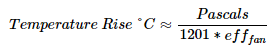
Likewise, the fan heat may be approximated in the SI form, using an Air Density Specific Heat Factor of 1201 J/m3K from the psychrometrics state point report:
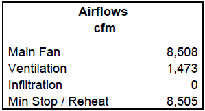
Airflows
The airflows section at the right of the screen shows the main fan airflow, ventilation rate, infiltration rate, and minimum airflow. In the example below, the main air handler is supplying 8508 cfm, of which 1473 cfm is ventilation. The rooms assume zero infiltration
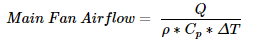
Main Fan airflow
Calculated using the sensible heat equation and the total load from the Fan Peak section.
Where:
Q is the grand total sensible load from the Fan Peak section of the checksums report
ρ is the air density (Design Psychrometrics report).
Cp is the specific heat (Design Psychrometrics report).
ΔT is the difference between the supply dry bulb and the room dry bulb. In cooling, the supply dry bulb is subtracted from the supply dry bulb. In heating, the room dry bulb is subtracted from the supply dry bulb. The supply dry bulb is entered in the system sizing properties and reported in the temperatures section of the checksums report. The room dry bulb is the space setpoint temperature (entered in the zone properties).
Ventilation
This is calculated based on the user input ventilation and the the sum OA or 62.1 ventilation calculations depending on the inputs in the room airflow properties and system sizing properties. It is reported at the time of fan peak.
Infiltration
The design infiltration is entered by the user in the Airflow Properties for each room. The reported infiltration is at time of fan peak and calculated using the weather file so may be different than the entered design infiltration.
Min Stop / Reheat
This is calculated based on the input in the terminal box properties. The terminal box properties can be found for the zone in the Configure Zone Equipment tab of Systems.
Engineering Checks
The engineering checks section shows the typical rule of thumb design values. The engineering checks are helpful to users who are looking for rule of thumb numbers, such as cfm/ton. If a specific rule of thumb number is desired, the engineer will have to back in a custom set of loads, schedules, and or supply air conditions to achieve those outcomes.
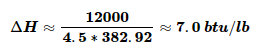
A typical value a user might look for is 400 cfm/ton. Such rule of thumb values have specific scenarios which they work, but rule of thumb values should not be expected in every scenario. See the document titled “Psychrometrics” in the Getting Started Guide and the example in the Load By Components Report help content.
In the situation above, the enthalpy change across the cooling coil would be:
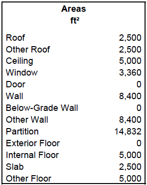
Areas
The areas section lists the total surface areas of all rooms part of the system.

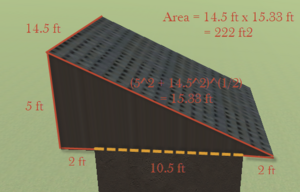
Roof
This is calculated from the centerline of each wall. For example, if the interior space of a room is 10 ft x 10 ft and the wall thickness is 0.5 ft, the roof area is calculated as 10.5 ft x 10.5 ft = 110.25 ft2. For a flat roof with an overhang, the overhang is not included in the roof area. For a sloped roof, the roof area is calculated as the sloped surfaces of the roof. For a sloped roof with an overhang, the entire sloped roof is included in the roof area. For example, if the interior space of a room is 10 ft x 10 ft and the wall thickness is 0.5 ft, the room has a shed roof with a peak height of 5 ft and an overhang of 2 ft, the roof area is calculated as follows.
Other roof
This is equal to the Roof area.
Ceiling
This is calculated from the centerline of each wall. For example, if the interior space of a room is 10 ft x 10 ft and the wall thickness is 0.5 ft, the ceiling area is calculated as 10.5 ft x 10.5 ft = 110.25 ft2.
Window
This is calculated from the dimensions/quantity of the windows. For example, if there are two windows and each have an area of 2 ft x 3 ft, the total window area is equal to 2 ft x 3 ft x 2 = 12 ft2. (Note: skylights and glass doors are included in the window category.)
Door
This is calculated from the dimensions/quantity of the doors. For example, if there are 4 doors with dimensions of 3 ft by 6 ft, the door area is equal to 3 ft x 6 ft x 4 = 72 ft2. Remember, the doors area only includes opaque doors. Glass doors are grouped with windows.
Wall
This is calculated from the centerline of each wall. For example, if the interior space of a room is 10 ft x 10 ft, the wall thickness is 0.5 ft, and the floor to floor height is 10 ft, the wall area of a square room is 10.5 ft x 10 ft x 4 walls = 420 ft2 (Note: the wall area is not decreased by the window and door areas if windows and doors are present.)
Below-Grade Wall
This is calculated from the centerline of each wall. For example, if the interior space of a room is 10 ft x 10 ft, the wall thickness is 0.5 ft, and the floor to floor height is 10 ft, the wall area of a square room is 10.5 ft x 10 ft x 4 walls = 420 ft2
Other Wall
This is equal to the Wall area.
Partition
This is calculated from the centerline of each interior wall. For example, if the interior space of a room is 10 ft x 10 ft and the wall thickness is 0.5 ft, the partition area is 10.5 ft x 10 ft = 105 ft2. There are two partition surfaces for each partition and both area accounted for in this area. The total area is 105 ft2 x 2 = 210 ft2.
Exterior Floor
This is calculated from the centerline of each wall. For example, if the interior space of a room is 10 ft x 10 ft and the wall thickness is 0.5 ft, the exterior floor area is calculated as 10.5 ft x 10.5 ft = 110.25 ft2. The bottom surface of an attic that extends past the room below it (due to a sloped roof with an overhang) is not included in the exterior floor area.
Internal Floor
This is calculated from the centerline of each wall. For example, if the interior space of a room is 10 ft x 10 ft and the wall thickness is 0.5 ft, the internal floor area is calculated as 10.5 ft x 10.5 ft = 110.25 ft2.
Slab
This is calculated from the centerline of each wall. For example, if the interior space of a room is 10 ft x 10 ft and the wall thickness is 0.5 ft, the slab area is calculated as 10.5 ft x 10.5 ft = 110.25 ft2.
Other Floor
This is equal to the interior floor area.