Component Selection Bar
Component Selection Bar
The component selection bar in the project is very similar to the component selection bar in the library. From the Configure Systems tab, you are able to add components and controls to the existing system configuration. Expand the components category to see all available coils, fans etc. and expand the controls category to see all available temperature and humidity controllers. The available components are filtered based on the system category.

Components
Clicking the Components button will expand the list of available components for the system type being created. Only available components will be populated in the components list. Components include fans, coils, heat pumps, energy recovery, unitary pieces of equipment, humidifiers, and heat exchangers.
In order to apply a specific component to the air path, you should click the component. When the component is selected, the diagram will indicate where the component can be placed with green buttons. If no green buttons appear, the component can’t be placed on the diagram. If a component is not compatible with the current system configuration, it will be greyed out.
Components can be arranged in different configurations to achieve different effects. For example, the supply fan can be placed before the cooling coil to create a blow through configuration or it can be placed after the cooling coil to create a draw through configuration.
Supply Fan
The Supply Fan is used to represent any type of constant volume fan that moves supply air in the system.
Library Type - Equipment Library - Fans - Constant Volume
Placement Rules: This fan can be placed in either the outside air path or the supply air path depending on system type. When the fan is placed in the outdoor air path, it will move the outdoor air. If the fan is in the supply air path, it will move both the mixed return and outdoor air. There can be a supply fan in both the outdoor air path and the supply air path.
Supply Fan VFD
The Supply Fan VFD is used to represent any type of variable volume fan that moves supply air in the system.
Library Type - Equipment Library - Fans - Variable Volume
Placement Rules: This fan can be placed in either the outside air path or the supply air path depending on system type. When the fan is placed in the outdoor air path, it will move the outdoor air. If the fan is placed in the supply air path, it will move both the mixed return and outdoor air. There can be a supply fan VFD in both the outdoor air path and the supply air path.
Return Fan, Return Fan VFD, Exhaust Fan, Exhaust Fan VFD
The Return Fan is used to represent any type of Constant Volume or Variable Volume fan that moves air from the system after the zones.
Library Type - Equipment Library - Fans - (Constant Volume, or Variable Volume)
The function of this fan will depend on it’s location in the loop.
If it is placed before the return air branch it gets identified as “RF-1” fan, if it is placed after the return air branch it gets identified as “EXF-1” fan.
When it is placed in the exhaust air path, it is used to remove air from the system and displace it outside. When the fan is placed in the return air path, it is used to move both the return air that will circulate back into the system as well as the exhaust air that is removed from the system.
Fan Sizing: Both fans types are sized for the maximum airflow of the system in the System Component Summary Report Fan section.
How to Track airflow through the fan:
Differences will be seen in the Visualizer Data values and identification.
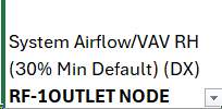
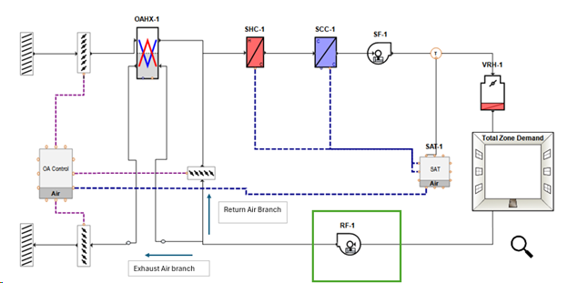
Here is an image of the “Return Fan” in the Data Visualizer System and in the Configure Systems - Components tab, placement in the loop.
Visualizer Variable name – This is one of the locations found as part of System Variable: System Airflow. By Selecting “System Airflow” all locations will be included in your output.


Configure Systems – Component Tab
Return Fan in system image

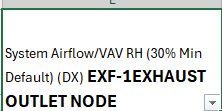
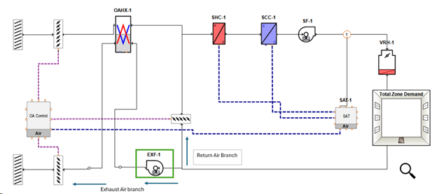
Exhaust Fan Application
Visualizer Variable name – This is one of the locations found as part of System Variable: System Airflow. By Selecting “System Airflow” all locations will be included in your output.


Configure Systems – Component Tab

Exhaust Fan in System Image

Cooling Coil
The cooling coil can be a chilled water coil or a DX cooling coil that is used to remove both sensible and latent energy to decrease the temperature and humidity of the supply air before it enters the space.
Library Type - Equipment - Cooling Coils - Water (Simple)
Equipment - Cooling Coils - Water (Detailed)
Equipment - DX Cooling Equipment - DX Cooling Equipment
Placement Rules: The cooling coil may be placed in the supply air path. Note, coils may not be placed in the outdoor air path. A separate DOA should be created and assigned to the system at the project level in order to condition outside air separately.
Heating Coil
The heating coil can be electric, hot water, gas, steam, multistage electric or multistage gas. The heating coil is used to add sensible energy to increase the temperature of the supply air before it enters the space.
Library Type - Equipment - Heating Coil - Electric
Equipment - Heating Coil - Hot Water
Equipment - Heating Coil - Gas
Equipment - Heating Coil - Steam
Equipment - Heating Coil - Multistage Electric
Equipment - Heating Coil - Multistage Gas
Placement Rules: The heating coil may be placed in the supply air path. Note, coils may not be placed in the outdoor air path. A separate DOA should be created and assigned to the system at the project level in order to condition outside air separately.
Air to Air Heat Pump
The Air to Air Heat Pump represents an air to air heat pump system that would be found in a custom air handler.
Library Type - Equipment - Heat Pumps - Air to Air Heat Pump
Placement Rules: The air to air heat pump can be placed in the supply air path. Note, coils may not be placed in the outdoor air path. A separate DOA should be created and assigned to the system at the project level in order to condition outside air separately.
Central Air to Air Heat Pump Unit
The central air to air heat pump represents a unitary packaged air to air heat pump component.
Library Type - Equipment - Packaged DX - Central Air to Air HP Unit
Placement Rules: The central air to air heat pump can be placed in the supply air path. Note, coils may not be placed in the outdoor air path. A separate DOA should be created and assigned to the system at the project level in order to condition outside air separately.
Central WSHP Unit
The central water source heat pump represents a unitary water source heat pump piece of equipment.
Library Type - Equipment - Packaged DX - Central WSHP Unit
Placement Rules: The central water source heat pump can be placed in the supply air path. Note, coils may not be placed in the outdoor air path. A separate DOA should be created and assigned to the system at the project level in order to condition outside air separately.
Heat Exchanger
The Heat Exchanger is used to transfer heat between two different air streams in the system. The supply side will use either the outdoor air or the supply air path. The exhaust side will always use the exhaust air path. Depending on the type of heat exchanger that is used, it can transfer either sensible energy (flat plate or sensible and latent: sensible only), latent energy (sensible and latent: latent only), or sensible and latent (desiccant or sensible and latent).
Library Type - Equipment - Heat Exchangers - Flat Plate
Equipment - Heat Exchangers - Desiccant
Equipment - Heat Exchangers - Sensible and Latent
Placement Rules: The Heat Exchanger can be placed in either the outdoor air path or the supply air path. A heat exchanger can be placed in both the outdoor air and supply air paths simultaneously. When the heat exchanger is placed in either the outdoor air or supply air paths, the exhaust air path will automatically be connected to the other side of the heat exchanger.
Series ERD
This component contains both a cooling coil (either DX or chilled water) and an air to air heat exchanger. The heat exchanger is used to precool the air before it enters the cooling coil and reheat that air after it leaves the cooling coil for dehumidification.
Library Type - Equipment - Cooling Coils - Water (Simple)
Equipment - Cooling Coils - Water (Detailed)
Equipment - DX Cooling Equipment - DX Cooling Equipment
Equipment - Heat Exchangers - Flat Plate
Equipment - Heat Exchangers - Dessiccant
Equipment - Heat Exchangers - Sensible and Latent
Placement Rules: This component can be placed in either the outside air or supply air path.
Changeover Bypass VAV
This is a unitary piece of equipment that includes a supply fan, DX cooling coil, heating coil, and an outdoor air mixer. The fan is constant volume but VAV dampers at each zone allow for a variable supply airflow. Any air not delivered to a space is recirculated to the main unit.
Library Type - Equipment - Packaged DX - Changeover-Bypass VAV
Placement Rules: The VAV (heat cool VAV bypass) can be placed in the supply air path. Note, coils may not be placed in the outdoor air path. A separate DOA should be created and assigned to the system at the project level in order to condition outside air separately.
Packaged DX
The Packaged DX component represents a packaged unit that contains a fan, cooling coil, and heating coil. The specific fan, cooling coil, and heating coil library members are designated in the equipment library for the unitary library member. Preheat and reheat coils can be added separately to the system using the appropriate heating coil and terminal device coil respectively.
Library Type - Equipment - Packaged DX - Packaged Cooling and Heating
Equipment - Packaged DX - Packaged Cooling and Heating (Water)
Placement Rules: The Unitary Heat Cool component can only be placed in the supply air path. Note, coils may not be placed in the outdoor air path. A separate DOA should be created and assigned to the system at the project level in order to condition outside air separately.
Packaged Heating Only
The packaged heating only component represents a packaged unit that contains a fan and heating coil. The specific fan and heating coil library members are designated in the equipment library for the unitary library member. Preheat and reheat coils can be added separately to the system using the appropriate heating coil and terminal device coil respectively. This component is only available in the Heating Only system category.
Library Type - Equipment - Packaged DX - Packaged Heating Only
Placement Rules: The Unitary Heat component can only be placed in the supply air path. Note, coils may not be placed in the outdoor air path. A separate DOA should be created and assigned to the system at the project level in order to condition outside air separately.
Packaged Cooling Only
The packaged cooling only component represents a packaged unit that contains a fan and cooling coil. The specific fan and cooling coil library members are designated in the equipment library for the unitary library member. This component is only available in the Cooling Only system category and as such, preheat and reheat coils will not be available to add to the system.
Library Type - Equipment - Packaged DX - Packaged Cooling Only
Equipment - Packaged DX - Packaged Cooling (Water)
Placement Rules: The Unitary Cool component can only be placed in the supply air path. Note, coils may not be placed in the outdoor air path. A separate DOA should be created and assigned to the system at the project level in order to condition outside air separately.
Humidifier
The humidifier heats water using either electricity or gas in order to create steam that is incorporated into the supply air using a fan to increase the humidity of the supply air.
Library Type - Equipment - Humidifiers - Electric Steam Humidifier
Equipment - Humidifiers - Gas Steam Humidifier
Placement Rules: The humidifier can only be added to the supply air path. It can be added either before or after other heating and cooling coils.
Direct Evaporative Cooler
The Direct Evaporative Cooler is used to precool supply air by evaporating water directly in the supply air stream. This decreases the sensible energy of the supply air but increases the latent energy.
Library Type - Equipment - Cooling Coils - Direct Evaporative Cooler
Placement Rules: The direct evaporative cooler can only be placed in the supply air path and can be placed before and after other coils.
Indirect Evaporative Cooler
The Indirect Evaporative Cooler is used to precool air with evaporating water without adding moisture to the air stream. Air is cooled by evaporating water and that air transfers heat with the supply air stream through an air to air heat exchanger. This decreases the sensible energy of the supply air without increasing the latent energy.
Library Type - Equipment - Cooling Coils - Indirect Evaporative Cooler
Placement Rules: The indirect evaporative cooler can only be placed in the supply air path and can be placed before and after other coils.
Controls And Sensors
Air loop controls and sensors must be applied to the system in order to define the location of temperature and humidity sensors and how the system is controlled. The sensor must be placed in the air path and connected to a component or components that will control the temperature or humidity.
For example, in order to control the temperature at the outlet of a draw through fan, the temperature sensor should be placed in the air path after the fan and the controller should be connected to both the cooling coil and the heating coil.
Temperature Sensor
A temperature controller is required. The temperature sensor is placed on the diagram to measure the temperature at that point in the air path. This controller should be connected to the OA control as well as each of the coils. Some system configurations will require multiple temperature controllers. For example, the dual duct system will require a separate temperature for the cooling coil on the cold deck and heating coil on the hot deck. Different control strategies can be used to maintain the temperature at the desired values. See the properties for more details.
Humidity Sensor
A humidity controller is optional. The humidity sensor is placed on the diagram to measure the humidity at that point in the air path. Different control strategies can be used to maintain the humidity at the desired values. See the properties for more details.