This program uses ASHRAE Heat Balance Method for calculations. See details of this method to understand the method history and development.
Air density, specific heat and latent heat of vaporization vary with barometric pressure and temperature. These values are assumed, at standard elevation, to be 0.075 lbs/ft3 ,0.241 btu/lb°F and 1073 btu/lb in the equations below. The program will vary these values based on the data provided with the Weather locations selected. The standard values shown here will change automatically to accommodate location elevations.
Latent load cannot be selectively removed by a typical cooling coil separate from sensible load. Air must be cooled to remove moisture according to the physics of air and metal. An exception would be the use of desiccants, which are another topic.
Sensible heat = air density x specific heat x airflow x change in dry bulb
|
1.085 = 60 x 0.075 x 0.241
|
|
Latent heat = air density x latent heat of vaporization x airflow x change in water ratio
|
|
0.69 = 60 x 0.075 x 1073 / 7000
|
|
Total heat = air density x airflow x change in enthalpy
|
|
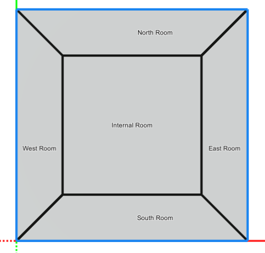
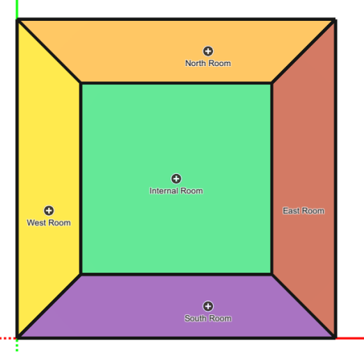
In order to show the loads in context of a file, an example file was made for demonstration. The example file is a 50' x 50' single story office building with 5 rooms. Each room is its own zone. The level is 13 feet tall with 40 percent exterior glazing. Weather is La Crosse, WI. A VAV Reheat system was applied with water coils.
|
|
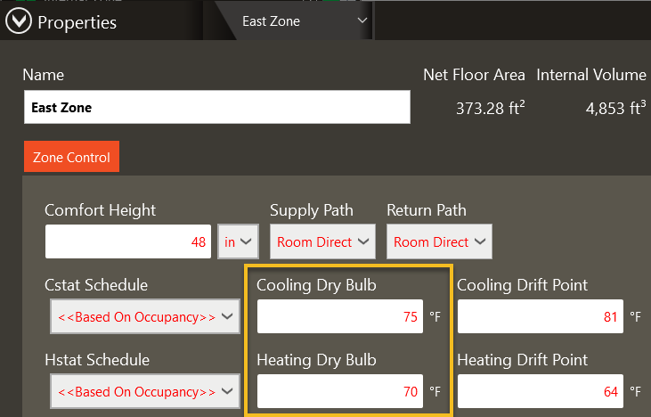
The zone design heating and cooling temperatures were set in the Zone Types.
|
|
The System Component Summary report is the main load design report for populating specifications and equipment schedules. This report provides the heating/cooling rate, airflow, air conditions and water conditions of each coil. The system airflows are calculated based on the heating and cooling airflows required by the rooms and zones, plus any system level overrides applied. System rules are then applied to decide how the heating and cooling airflows should relate. For example, in a constant volume system, the cooling airflow and heating airflow must be the same, so both are set equal to the higher airflow, causing oversizing on either heating or cooling.
|
|
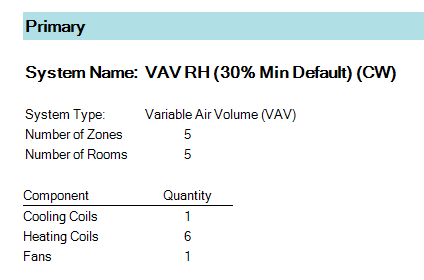
In this example, there are five zones, five VAV boxes, five rooms, one cooling coil, six heating coils (five boxes plus system preheat), and one fan.
|
The Cooling Coils section lists all cooling coils. The main cooling coil is named SCC-1. The main cooling coil has a design airflow of 2,148 cfm, of which 295.7 cfm is ventilation. The entering dry bulb and humidity ratio are 77.6°F and 70.43 gr/lb. The leaving dry bulb and humidity ratio are 52.9°F and 60.86 gr/lb. The fan heat in this situation is 2.1°F, so the cooling coil must produce 52.9°F to overcome the fan heat to deliver 55°F. Therefore, the cooling coil reduced the dry bulb by 24.7°F = 77.6 - 52.9°F and reduced the humidity ratio by 9.57 gr/lb = 70.43 - 60.86 gr/lb. Using a psychrometric chart [see Psychrometrics (HVAC Fundamentals)] the entering enthalpy is approximately 29.6 btu/lb and the leaving enthalpy is approximately 22.0 btu/lb, with a difference of approximately 7.6 btu/lb = 29.6 - 22.0 btu/lb.
|
|
The main cooling coil sensible capacity is:
|
|
55,200 btuh = 1.040 x 2148 x (77.6 - 52.9)
|
|
1.040 is used because the specific heat and density are different from standard conditions.
|
|
The main cooling coil total capacity is:
|
|
68,900 btuh = 4.22 x 2,148 cfm x (29.6 - 22.0 btu/lb)
|
|
4.22 is used because the density is different from standard conditions.
|
|
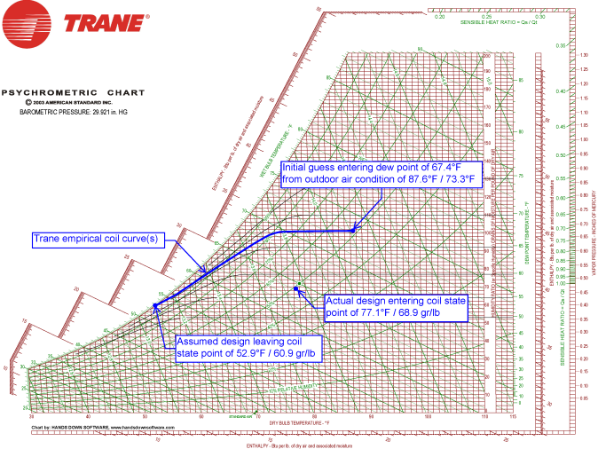
Version 4.13.207 and later can automatically solve the psychrometric loop (if the loop is possible to be closed). Version 4.12.74 and earlier could not. In all versions, the default process is to have the user assume the design supply air temperatures. When this path is used, the leaving cooling coil state point is calculated using the same TRACE 700 coil curves, except that the initial guess for the entering dew point is set equal to the highest enthalpy outdoor air dew point. The design leaving coil state point is based on the Trane coil curves using this initial guess entering dew point. The design entering coil state point applies the actual loads, outdoor air mixture, and zone state points.
|
|
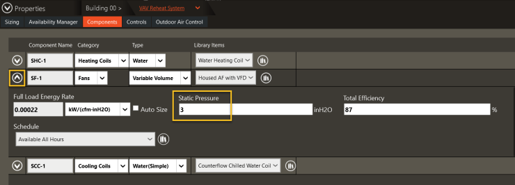
The leaving cooling coil temperature is equal to the input design cooling temperature minus the fan heat. Fan heat is load that must be offset by the cooling coil. Heating Design does not include fan heat, even though in real life the fan heat would supplement the heating coil like any other internal load. Fan heat can be calculated using the power equation of fans, since all fan energy dissapates into the air stream, whether as impellor inefficiency or duct friction. To ignore fan heat, input a static pressure of 1 pascal or 0.01 inch on the fan.
|
|
Fan heat = static pressure / (conversions x air density x specific heat x efficiency)
|
|
1.085 = 60 x 0.075 x 0.241
|
|
Fan heat = inches pressure / (2.5 x 1.085 x efficiency)
|
The main cooling coil ventilation load is not as obvious to hand calculate, because ventilation load is defined based on the difference in state points between the outdoor air and the zones. In this example, the outdoor air dry bulb and wet bulb are 87.6°F and 73.3°F, which is a humidity ratio of 101.1 gr/lb. The room dry bulb and relative humidity are 75.0°F / 50 %, which is a humidity ratio of 65.5 gr/lb. Using a psychrometric chart [see Psychrometrics (HVAC Fundamentals)] the outdoor air enthalpy is approximately 36.9 btu/lb and the zone enthalpy is approximately 28.2 btu/lb, with a difference of approximately 8.7 btu/lb = 36.9 - 28.2 btu/lb.
|
|
11,300 btuh = 4.39 x 295.7 cfm x (36.9 - 28.2 btu/lb)
|
|
4.39 is used because the density is different from standard conditions.
|
|
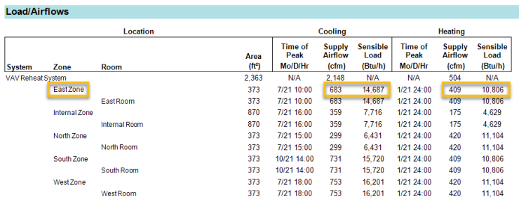
The Heating Coils section lists all heating coils. In the example below, the terminal heating coil for the East Zone is 17.3 MBh (17,300 btuh). The airflow rate is 409 cfm. The entering air to the VAV box is 55°F from the main air handler. The design leaving temperature from the VAV box in heating mode is 95°F. Because nothing about the system forced an override onto the final heating design airflow, the 409 cfm in the Heating Coils table matches the 409 cfm heating airflow for the East Zone in the Load/Airflows table.
|
|
The East Zone heating coil capacity is:
|
|
17,300 btuh = 1.057 x 409 cfm x (95°F - 55°F)
|
|
1.057 is used because the specific heat and density are different from standard conditions.
|
|
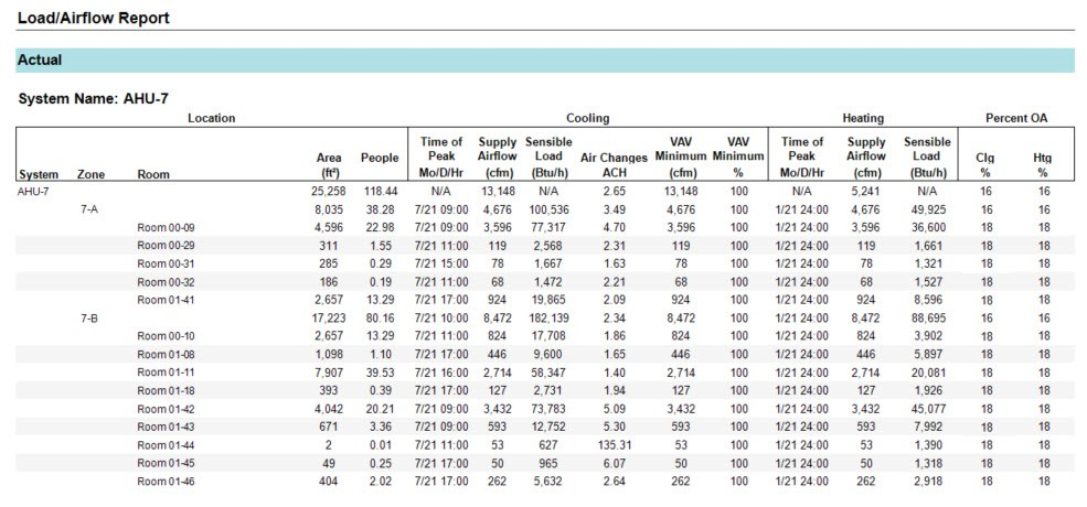
The Load/Airflows section of the System Component Summary shows the sensible cooling and heating loads of each room and zone. Only the sensible loads are shown here because sensible loads are used to determine airflows. The Load/Airflows table shows the cooling and heating airflows needed to meet the zone and room sensible loads according to the assumed cooling and heating supply air temperatures.
|
|
The East Zone cooling sensible load is:
|
|
14,687 btuh = 1.075 x 683 cfm x (75°F - 55°F)
|
|
1.075 is used because the specific heat and density are different from standard conditions.
|
|
The East Zone heating sensible load is:
|
|
10,806 btuh = 1.057 x 409 cfm x (95°F - 70°F)
|
|
1.057 is used because the specific heat and density are different from standard conditions.
|
|
10,806 btuh in the Load/Airfows table is lower than the East Zone VAV box capacity in the Heating Coils table above because the VAV box is also require to raise the supply air from 55°F. Notice that the Load/Airflows load is based on the East Zone heating dry bulb of 70°F and not the entering supply air dry bulb of 55°F. The Load/Airflows table shows the user how to size the maximum and minimum airflows for each VAV box, assuming no other overrides or restrictions have been applied. For the East Zone VAV box, the design airflow with the damper fully open is 683 cfm, and the minimum stop position is 409 cfm (60 %). Because 60 % may seem high to some users or regulators, it may be recommended the increase the design heating supply dry bulb to the zone in Configure Systems or Configure Zone Equipment, whichever is governing the zone heating supply dry bulb.
|
inputting and verifying the design supply air temperatures requires attention to detail. The first question to ask if if the system has a main air handler component and then a terminal device component. If the system has a main air handler component, the next question to ask is if the purpose of the main air handler is strictly to act as a dedicated outdoor air unit (see Dedicated Outdoor Air (DOA) Units) which is not the same as a 100 % outdoor air conditioning system (see 100% Outside Air Units). The next question to ask is how the leaving temperatures of the main air handler interact with the leaving temperatures of the terminal devices.
|
|
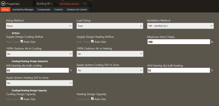
The parameters for the main air handler can be found in Configure Systems -> Properties -> Sizing tab. This scenario is a "typical" VAV reheat system. The leaving cooling design temperature is 55°F and is set to YES to be applied to the zone for sizing: this means that the main air handler will overrule the cooling design temperature in Configure Zone equipment for sizing airflow. The airflows for the zones will be determined based on their cooling sensible loads and the leaving 55°F supply air. In this example, the design leaving cooling supply temperature from the VAV boxes is 55°F, which appeared previously in the Cooling Coils table. The leaving heating design temperature was set equal to the cooling design temperature is set to NO to be applied to the zone for sizing. The terminal VAV box has a heating coil, and the terminal heating coil leaving temperature will be used to size the heating airflow. The main air handler in heating mode is simply acting as a pretreatment device to not send frigid air down the ducts. The main air handler's heating coil will be sized to heat all air requested to 55°F, but the main air handler, itself, will not govern the heating design airflow.
|
|
The parameters for the terminal conditioning device can be found in Configure Zone Equipment -> Properties-> Zone Sizing tab. The cooling design supply dry bulb was set equal to the main air handler design cooling dry bulb to remove confusion. Because the main air handler was set to NO for applying the heating design supply dry bulb to the zones, the airflows to the zones are determined based on the Zone Sizing input. In this example, the design leaving heating supply temperature from the VAV boxes is 95°F, which appeared previously in the Heating Coils table.
|
|
The Terminal Device tab shows additional parameters. In this example, if the heating design airflow was less than 30 percent of the cooling design airflow, the heating design airflow would be increased to 30 percent. The cooling VAV minimum, however, will not increase the total design airflow, as VAV dampers are not able to pull air from the air handler. In other words, if the design cooling airflow was 1,000 cfm and the VAV minimum was set to 2,000 cfm, the VAV minimum will not increase the design airflow to 2,000 cfm.
|
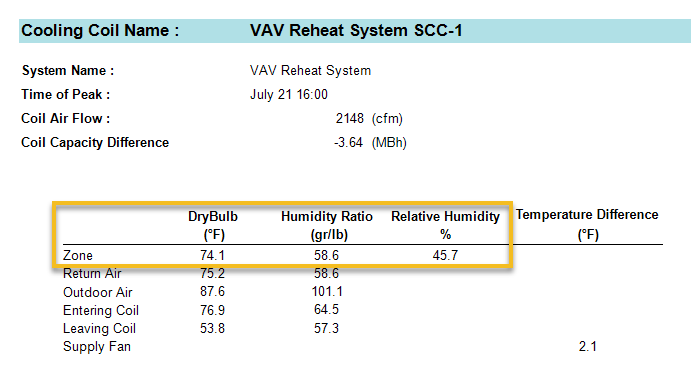
The Design Psychrometrics report shows the cooling coil state points during the Simulation Peak (see Ideal Peak Versus Simulation Peak, and the various peak times.). Here, the user can see the expected relative humidity of the zone with the current system and plant configurations, and the impact of background equipment curves, coil curves and oversizing on humidity control. In this example, the zone is around 50 % relative humidity as expected. The fan heat is 2.1°F as previously discussed. If this system were a constant volume system, oversizing on the cooling coil would cause a loss of control on humidity in the space, since a constant volume system can only increase the cooling supply air temperature to unload. User overrides and safety factors could cause unanticipated outcomes in this report.
|
|
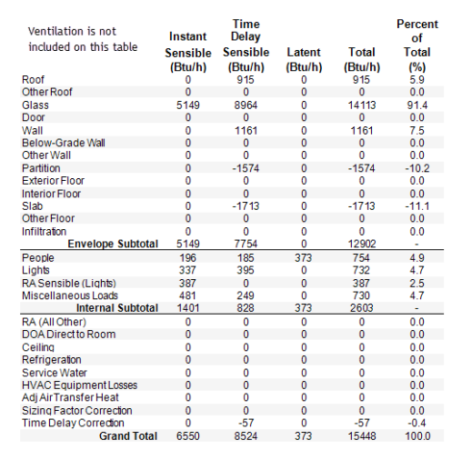
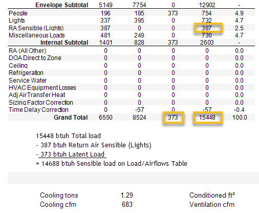
A breakdown of loads for rooms and zones can be found on the Room/Zone Heating/Cooling by Component reports. The Grand Total at the bottom of the table is the total load the room/zone contributes to the building minus ventilation. The room will not feel the RA Sensible (Lights) which is subtracted in the Load/Airflows table in the System Component Summary report. Likewise, the room does not feel the ventilation load, which is not even listed. In this example, the total sensible load of the East Zone to determine the cooling airflow is 6,550 + 8,524 - 387 = 14,687 btuh, equal to the cooling sensible load for the East Zone listed on the Load/Airflows table of the System Component Summary report. Latent load treatment is incidental to the supply air dew point.
|
|
The East Zone cooling sensible load for airflow is:
|
|
Instant Sensible + Time Delay Sensible - RA Sensible (Lights) = design sensible load for airflow
|
|
6,550 + 8,524 - 387 = 14,687 btuh, equal to the cooling sensible load for the East Zone listed on the Load/Airflows table of the System Component Summary report.
|
|
14,687 btuh = 1.075 x 683 cfm x (75°F - 55°F), showing the same airflow as on the Load/Airflows table of the System Component Summary report.
|
|
1.075 is used because the specific heat and density are different from standard conditions.
|
|
The Engineering Checks are at the bottom of the Room/Zone Heating & Cooling by Component reports. The Cooling/Heating total at the bottom of the table, however, does include the RA Sensible (Lights) because that load is sourced from this zone/room.
|
|
Because there is only one design cooling airflow to a room, the sensible loads and latent loads should balance using the same airflow. Thus, the air needs to be dry enough at the sensible cfm to address the internal latent loads. The program will not auto-determine the optimal supply air dewpoint at this time, so iteration on a psychrometric chart is required.
|
|
btuh Sensible = btuh Latent
|
|
dW is the change in humidity ratio in gr/lb
|
|
dT is the change in dry bulb in °F
|
|
Drawing a line on a psychrometric chart with slope dW/dT which passes through the design space relative humidty and dry bulb will provide a line of suitable supply air state points to condition the room.
|
|
A breakdown of the outside air analysis can be found on the Outside Air / ASHRAE Standard 62.1 Summary report. The system ventilation rate is calculated as either the sum of room ventilation rates or the ASHRAE 62.1 multi-zone method. The parameters for the ASHRAE 62.1 calculation are displayed. The delivered ventilation to each zone is displayed on the Zone Heating/Cooling Loads by Component reports. This rate differs from the requested ventilation rates in the Room Heating/Cooling Loads by Component reports because the main air handler is only able to deliver one mixture to all zones: it cannot deliver 20 % outdoor air to one zone and then 90 % outdoor air to another zone. In the example below, the Internal Zone has the lowest Evz value of 0.669. Thus, the overall outdoor air was inflated according to 198 cfm / 0.669 = 296 cfm, resulting in 13.8 % outdoor air. See ASHRAE 62.1 for more detail on this calculation.
|
|
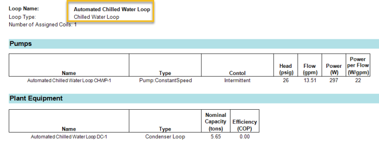
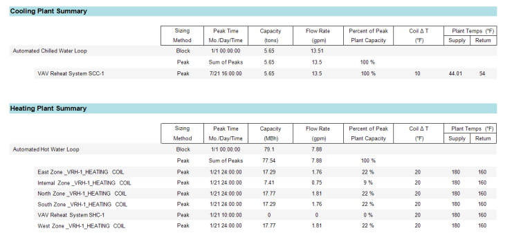
The plant sizing will appear in the System Component Summery Report and the Plant Summary report. The Pumps and Plant Equipment tables are on the System Component Summary report.
|
The Cooling and Heating Plant Summary tables appear on the Plant Summary report. Plants that are set to "Peak" sizing will simply add up all peak coil loads from the Ideal Loads Peak calculation. Plants that are set to "Block" sizing will perform an additional calculation to determine the flow required to meet the block load of all the coils in the Simulation Peak calculation (See Ideal Peak Versus Simulation Peak, and the various peak times.) Coil approach matters in the block sizing for calculating the required flow rate through the coils to push the heat through the coil.
|
|
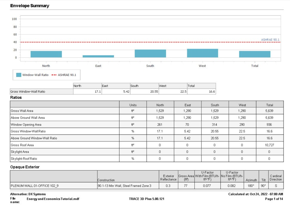
The Envelope Summary report
|
|
The table only lists the four cardinal directions. To account for walls that are not directly facing one of the four cardinal directions the categories each cover 90° angles.
|
|
The Load/Airflows report groups information from the System Component Selection Summary, System Cooling and Heating Checksums, Loads by Components, and other reports to provide a quick reference to the most important information.
The Peak Load Summary report lists the time of peak, OA Conditions, Room/Zone Drybulb, Supply Airflow Drybulb, Sensible and Latent Load for both Cooling and Heating peak for all rooms and zones.
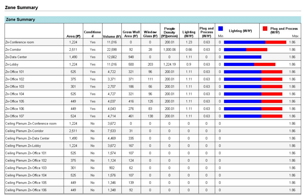
The Zone Summary report shows a table comparing the key zone parameters.
|
|
System Cooling and System Heating Checksum Reports
|
|
Note: In versions 5.20.117 and newer, the checksums report won't be available for certain configurations. Because the system checksums reports show system level information, the checksums report is not available for zone level systems. In addition, it is not available if the main AHU level coil has zero capacity. For example, if teh return air temperature of a VAV RH system at heating design is greater than the preheat coil setpoint temperature, the preheat coil will not be needed and will be sized with zero capacity. In this case, the heating checksums for this system will not be available because there is no system level heating coil.
|
|
The system checksums report will also not be available for DOAS systems and other systems that are sized based on ventilation and/or latent loads. When a system is sized based on ventilation load, the envelope and internal loads are not used to size the system so the information on the checksums report is not useful and will not be shown in this case.
|
|
There are two different reports, the System Cooling Checksums and the System Heating Checksums.
|
|
The two largest sections of this report are the Coil Peak, and Fan Peak sections. The Coil Peak section shows all of the loads on the coil at the time of system coil peak. The time of system peak as well as the outdoor air conditions at that time are reported at the top. Dry bulb and wet bulb temperatures are reported in degrees F in IP and degrees C in SI. The humidity ratio is reported in grains/lb in IP and kg water/kg air in SI.
|
|
The Fan Peak section shows all the sensible loads that are used for sizing the fan. If the fan is sized based on block, the loads will be summed for each of the zones at the time of system fan peak. If the fan is sized based on peak, the loads will be summed for each of the zones at each individual zone peak time.
|
|
There are 6 different columns in the Coil Peak section.
|
|
Instant Sensible: This is the sensible load to the space at the time of peak. This is a load that enters the space or is generated in the space at the peak hour.
|
Time Delay Sensible: This is the sensible load due to radiant components of the load. The radiant components of internal loads are defined in the internal load libraries and in the internal load templates. There are also radiant components of envelope loads. These radiant loads are absorbed by the surfaces in the space and retransmitted at later hours. The time delay sensible load is an estimate of the current hour’s load and previous hours’ loads that are impacting the space at the time of peak. For more details on these calculations, see the Energy Plus Engineering Reference Manual in section 23.2 Component Loads Summary. Energy Plus Documentation
|
|
Latent: This is the latent component of the load that impacts the space at the time of peak. The latent component of internal loads are defined in the internal loads library and can be edited in the internal load template in the project.
|
|
Total: This is simply the sum of the instant sensible, time delay sensible, and latent loads.
|
|
Percent of Total: This is calculated by
|
|
(Percent of Total) = (Total)/(Grand Total)*100
|
|
Btu/h per ft2 (or W/m2): This is a ratio of the total load and the area of the related surface. The surfaces used for each load component are listed in the table below. The area for each of these surfaces can be found in the Areas section of the report as well as the Related Area column of the Fan Peak section.
|
|
The fan peak section reports the loads at the time of fan peak. This is reported using the cooling peak loads in both the cooling and heating checksums reports.
|
|
There are 5 different columns in the Fan Peak section
|
|
Instant Sensible: This is the same as the Coil Peak section except at the time of fan peak rather than at the time of coil peak. If the coil and fan peak at the same time, these values will be the same.
|
|
Time Delay Sensible: This is the same as the Coil Peak section except at the time of fan peak rather than at the time of coil peak. If the coil and fan peak at the same time, these values will be the same.
|
|
Total Sensible: This is the sum of the instant sensible and the time delay sensible.
|
|
Percent of total: This is calculated by
|
|
(Percent of Total) = (Total Sensible)/(Grand Total)*100
|
|
Related Area: This is the area used in the Btuh per ft2 (W/m2) column in the Coil Peak section. This area relates to the particular load component. The area used for each component can be found in the table below. Keep in mind, if a surface doesn't directly impact the load in the space, it will not be included in the areas. For example, if all spaces on a particular system have a ceiling plenum, the roof won't directly impact the space and the roof area will report as 0.
|
|
Component
|
Defined in Project
|
Related Area
|
|
Roof
|
Roof surface defined in Create Building
|
Roof
|
|
Other Roof
|
not yet supported
|
Other Roof
|
|
Glass
|
Windows, skylights, and glass doors defined in Create Building.
|
Window
|
|
Door
|
Opaque doors defined in Create Building (Glass doors are in the glass category)
|
Door
|
|
Wall
|
Exterior walls defined in Create Building for above ground levels
|
Wall
|
|
Below-Grade Wall
|
Exterior walls defined in Create Building for basement levels
|
Below-Grade Wall
|
|
Other Wall
|
not yet supported
|
Other Wall
|
|
Partition
|
Interior walls defined in Create Building
|
Partition
|
|
Exterior Floor
|
Floor exposed to outside air (such as a cantilevered space)
|
Exterior Floor
|
|
Internal Floor
|
Floors between rooms on different levels
|
Internal Floor
|
|
Slab
|
Ground contact slab
|
Slab
|
|
Other Floor
|
not yet supported
|
Other Floor
|
|
Infiltration
|
Unconditioned outdoor air defined in the Airflows properties in Create Building
|
Wall
|
|
People
|
People defined in the Internal Loads properties in Create Building
|
*
|
|
Lights
|
Portion of the lighting load to the space defined in the Internal Loads properties in Create Building
|
*
|
|
Miscellaneous Loads
|
Miscellaneous loads defined in the Internal Loads properties in Create Building
|
*
|
|
Ventilation
|
See calculation method below
|
n/a
|
|
DOAS Direct to Zone
|
Load due to a Zone DOAS defined on the Select Systems tab. This is a DOAS that serves a zone directly. The System Level DOAS selected on the Configure Systems tab will not impact this output since the conditioned outdoor air is delivered to the main system coils and not directly to the zone. This type of DOAS will affect the ventilation component on this report instead. Both the zone level DOAS and the multi system DOAS will not impact this report because these serve only zone level systems and zone level systems are not reported on the System Checksums.
|
n/a
|
|
Ceiling
|
Ceiling load due to either a drop ceiling between a space and the plenum above, or a ceiling between a space and the space on the level above when there is no drop ceiling or plenum
|
Ceiling
|
|
Refrigeration
|
not yet supported
|
*
|
|
Service Water
|
not yet supported
|
*
|
|
HVAC Equipment Losses
|
not yet supported
|
n/a
|
|
Adj Air Transfer Heat
|
Load due to adjacent air being transferred between zones or systems.
|
|
|
Supply Fan Heat
|
Motor heat pickup from the supply fan defined by the motor heat to air field in the fan library and the fan full load energy rate defined in the fan library and system component properties
|
n/a
|
|
Time Delay Correction
|
This is the difference between the peak sensible load and the sum of the instant and time delayed sensible loads. This is used to compare the sum of the loads to the estimated time delay.
|
n/a
|
|
Sizing Factor Correction
|
This comes from the sizing factor applied on the system sizing properties for the Cooling/Heating Design Capacity if the capacities are not auto sized.
|
n/a
|
|
Over/undersizing
|
This is the difference between the sum of zone loads (at the system peak time so this is a block load for block systems) and the actual system load. This difference accounts for upsizing in the system due to things like increased airflow to accomodate 62.1 ventilation rates and upsizing cooling supply airflow for heating dominant systems. There can also be over/undersizing when the user enters a supply airflow.
|
n/a
|
|
RA Sensible (Lights)
|
Portion of the lighting load to the return air defined in the Internal Loads properties in Create Building (see calculation method below)
|
*
| |
|
*Total area of all rooms on the system (found in the engineering checks section of the loads by component reports)
|
|
System Checksum Calculations
|
|
Sensible Load = Return air component of lighting load - RA exhaust
|
|
RA exhaust = (%OA/100) * coil flow * Cpmoistair * (RAdb - Rmdb)
|
|
Sensible Load = Cp*rho*cfm_SA*(T_MA – T_RA)
|
|
Cp is the moist air heat capacity (Design Psychrometrics report)
|
|
Rho is the standard air density adjusted for elevation (Design Psychrometrics report)
|
|
Cfm_SA is the supply air volume flow rate at ideal loads peak (Design Psychrometrics report)
|
|
T_OA is the outdoor air drybulb at ideal loads peak (Coil Peak Dry Bulb temperature from Checksums report)
|
|
T_zone is the zone air drybulb at ideal loads peak (Defined in the zone properties in the Create Zones tab)
|
|
Latent Load = Total Load – Sensible Load
|
|
Total Load = rho*cfm_SA*(h_MA – h_RA)
|
|
H_OA is the outdoor air enthalpy calculated psychrometrically from the outdoor air drybulb at ideal loads peak and the outdoor air humidity ratio at ideal loads peak (Coil Peak Dry Bulb temperature and humidity ratio from Checksums report)
|
|
H_zone is the zone enthalpy calculated psychrometrically from the zone air dry bulb at ideal loads peak and zone air humidity ratio at ideal loads peak (Coil Peak Dry Bulb temperature and humidity ratio from Checksums report)
|
|
Supply: This is the main supply temperature entered in the system sizing properties. Keep in mind that this is the system level supply air temperature which is not necessarily the supply air temperature to the space. For example, the VAV RH (30% Min Default) (DX) system has a main heating and cooling coil as well as a zone level terminal box reheat coil. The system is designed so the main heating coil preheats the air to 55 F and the reheat coil heats it the rest of the way to 90 F. Because the reheat coil is zone level, it is not considered in this report so the main heating supply temperature is reported as 55 F because this is the leaving preheat coil temperature.
|
|
Return: This is the return air temperature from the space calculated by the program
|
|
Mixed Air: This is the mixed air temperature calculated using the mixed air equation for the return air, outdoor air, and percent outdoor air
|
|
MA = (%OA/100)*T_OA + (1-%OA/100)*T_RA
|
|
Keep in mind that the mixed air temperature is calculated at the time of coil peak, not at the time of fan peak so the %OA used in this calculation may not be the same as the %OA reported in the Aiflows section of this report if the coil and the fan do not peak at the same time.
|
|
Fan Heat TD: This is the fan heat pick up in due to fan motor heat
|
|
Main Fan airflow: Calculated using the sensible heat equation and the total load from the Fan Peak section.
|
|
cfm = q/(rho*cp*(T_supply - T_room)/60[min/hr]
|
|
q is the grand total sensible load from the Fan Peak section of the checksums report
|
|
rho is the air density (Design Psychrometrics report)
|
|
cp is the specific heat (Design Psychrometrics report)
|
|
T_supply is the supply air temperature (entered in the system sizing properties and reported in the temperatures section of the checksums report)
|
|
T_room is the space setpoint temperature (entered in the zone properties)
|
|
60 is a conversion factor from hours to minutes since cfm is in cubic feet per minute
|
|
Ventilation: This is calculated based on the user input ventilation and the the sum OA or 62.1 ventilation calculations depending on the inputs in the room airflow properties and system sizing properties. It is reported at the time of fan peak.
|
|
Infiltration: The design infiltration is entered by the user in the Airflow Properties for each room. The reported infiltration is at time of fan peak so may be different than the entered design infiltration.
|
|
Min Stop / Reheat: This is calculated based on the input in the terminal box properties. The terminal box properties can be found for the zone in the Configure Zone Equipment tab of Systems.
|
|
% OA = ventilation / main fan (at time of fan peak)
|
|
Cfm/ft2 = main fan / (people * ft2/person)
|
|
Btuh/ft2 = Grand Total from Coil Peak / (people * ft2/person)
|
|
Cfm/ton = main fan / (Grand Total from Coil Peak [Btu/h] /12000 [Btuh/ton])
|
|
Ft2/ton = (people * ft2/person) / (Grand Total [Btu/h] /12000 [Btuh/ton])
|
|
People – This is the sum of people in all rooms on the system rounded to the nearest whole person
|
|
Ft2/person – this is the sum of the interior area of each room on the system divided by the sum of people in all rooms
|
|
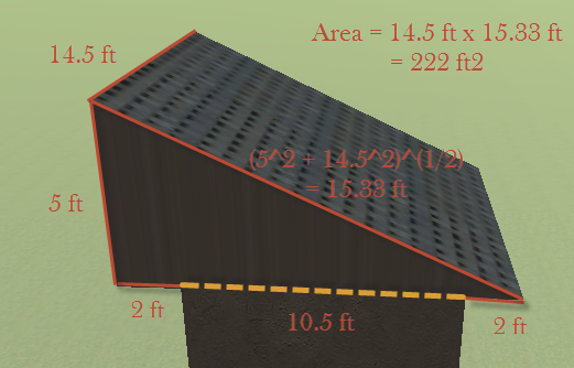
Roof – This is calculated from the centerline of each wall. For example, if the interior space of a room is 10 ft x 10 ft and the wall thickness is 0.5 ft, the roof area is calculated as 10.5 ft x 10.5 ft = 110.25 ft2. For a flat roof with an overhang, the overhang is not included in the roof area. For a sloped roof, the roof area is calculated as the the sloped surfaces of the roof. For a sloped roof with an overhang, the entire sloped roof is included in the roof area. For example, if the interior space of a room is 10 ft x 10 ft and the wall thickness is 0.5 ft, the room has a shed roof with a peak height of 5 ft and an overhang of 2 ft, the roof area is calculated as follows.
|
|
Other roof – This is equal to the Roof area.
|
|
Ceiling – This is calculated from the centerline of each wall. For example, if the interior space of a room is 10 ft x 10 ft and the wall thickness is 0.5 ft, the ceiling area is calculated as 10.5 ft x 10.5 ft = 110.25 ft2.
|
|
Window – This is calculated from the dimensions/quantity of the windows. For example, if there are two windows and each have an area of 2 ft x 3 ft, the total window area is equal to 2 ft x 3 ft x 2 = 12 ft2. (Note: skylights and glass doors are included in the window category.)
|
|
Door – This is calculated from the dimensions/quantity of the doors. For example, if there are 4 doors with dimensions of 3 ft by 6 ft, the door area is equal to 3 ft x 6 ft x 4 = 72 ft2. Remember, the doors area only includes opaque doors. Glass doors are grouped with windows.
|
|
Wall – This is calculated from the centerline of each wall. For example, if the interior space of a room is 10 ft x 10 ft, the wall thickness is 0.5 ft, and the floor to floor height is 10 ft, the wall area of a square room is 10.5 ft x 10 ft x 4 walls = 420 ft2 (Note: the wall area is not decreased by the window and door areas if windows and doors are present.)
|
|
Below-Grade Wall – This is calculated from the centerline of each wall. For example, if the interior space of a room is 10 ft x 10 ft, the wall thickness is 0.5 ft, and the floor to floor height is 10 ft, the wall area of a square room is 10.5 ft x 10 ft x 4 walls = 420 ft2
|
|
Other Wall – This is equal to the Wall area.
|
|
Partition – This is calculated from the centerline of each interior wall. For example, if the interior space of a room is 10 ft x 10 ft and the wall thickness is 0.5 ft, the partition area is 10.5 ft x 10 ft = 105 ft2. There are two partition surfaces for each partition and both area accounted for in this area. The total area is 105 ft2 x 2 = 210 ft2.
|
|
Exterior Floor – This is calculated from the centerline of each wall. For example, if the interior space of a room is 10 ft x 10 ft and the wall thickness is 0.5 ft, the exterior floor area is calculated as 10.5 ft x 10.5 ft = 110.25 ft2. The bottom surface of an attic that extends past the room below it (due to a sloped roof with an overhang) is not included in the exterior floor area.
|
|
Internal Floor – This is calculated from the centerline of each wall. For example, if the interior space of a room is 10 ft x 10 ft and the wall thickness is 0.5 ft, the internal floor area is calculated as 10.5 ft x 10.5 ft = 110.25 ft2.
|
|
Slab – This is calculated from the centerline of each wall. For example, if the interior space of a room is 10 ft x 10 ft and the wall thickness is 0.5 ft, the slab area is calculated as 10.5 ft x 10.5 ft = 110.25 ft2.
|
|
Other Floor – This is equal to the interior floor area.
|
|
Trace 3D Plus performs a calculation to compare calculated load of the cooling coil at its design airflow to the auto sized airflow based load (using the equation below).
|
|
Qairflowadjustmentsensbile = RhoAir * CpMoistAir * CoilVolFlow * (RmDb - SAT) - PeakSensibleLoad
|
|
If there is a positive value then the coil is oversized and, likewise, a negative value is undersized. Usually, it will be oversized unless the user sets the airflow. This adjustment is necessary because the peak sensible load doesn't include any of the effects of any sizing factors like the system 62.1 adjustment. The coil sees the return portion of the space loads, ventilation load, and the latent loads (for total) which will be larger than just the peak sensible load that exists in the spaces.
| |
