Properties
The properties section gives all the details of the system and its various components. Here, equipment libraries can be selected for each component and sizing and control information can be entered. Most of the properties can be edited however properties specific to a piece of equipment (i.e. coil full load energy rate) are read only and can only be edited in the equipment library.
|
|
| |||||||
|
|
|
|
|
|
|
|
|
Sizing
The Sizing tab contains information for system level sizing properties.
|
|
|
|
|
|
|
|
Sizing Method
The system can be sized based on the system block or system peak.
Block: A block system is based on the maximum simultaneous cooling load of all the rooms and includes the sensible and latent loads due to lights, infiltration, people, miscellaneous, solar, external conduction loads, and ventilation (outside) air (if the ventilation is delivered directly to the room).
Peak: A peak system is based on the sum of the individual room peak cooling loads that may or may not occur at the same time. Peak includes the sensible and latent loads due to lights, infiltration, people, miscellaneous, solar, external conduction loads, and ventilation (outside) air (if the ventilation is delivered directly to the room).
Load Sizing
Sizing can be based on either total load, sensible load, or the ventilation requirement.
Total: The system air flow rate is sized based on the combined sensible and latent load. This is common for most system types.
Sensible: The system air flow rate is sized based on the sensible load only and not the latent component. This is common when there is another piece of equipment used to condition the humidity loads.
Ventilation requirement: The system air flow rate is sized based on the system ventilation requirement. This is common for AHU coils associated with induction and chilled beam system types.
Ventilation Method
Zone Sum – Sum of Outdoor Air: The Sum of Outdoor air totals the ventilation requirements for all of the zones on the system to calculate the ventilation requirement for the system.
VRP – ASHRAE 62.1: The ventilation rate procedure uses the multizone calculations found in ASHRAE 62.1 to calculate the ventilation requirement for the system. If the ventilation at the building level is set to 62.1, make sure to set this ventilation method to 62.1 as well.
Airflow
The airflow section contains information for system level airflow sizing.
Supply Design Cooling Airflow
|
Default: Autosize
|
|
Min Max: 0–infinity
|
|
Units: m3/sec, cfm, cfm/sq•ft (Floor), (m3/s)/sq•m (Floor), % Clg Airflow, cfm/ton, m3/hr•sq•m (Floor), cm3/sec, (m3/s)/kW, m3/hr•kW, m3/s•W, cm3/sec, m3/hr
|
The Supply Design Cooling Airflow can be autosized by checking the Auto Size box. If the Auto Size box is unchecked, the design airflow for the system can be entered.
Supply Design Heating Airflow
|
Default: Autosize
|
|
Min Max: 0–infinity
|
|
Units: cm3/sec, m3/hr, (m3/s)/kW, m3/hr•kW, cm3/sec, m3/hr•sq m (Floor), m3/sec, cfm, cfm/sq•ft (Floor), (m3/s)/sq•m (Floor), % Clg Airflow, m3/s•W, cfm/ton, % Htg Airflow
|
The Supply Design Heating Airflow can be autosized by checking the Auto Size box. If the Auto Size box is unchecked, the design airflow for the system can be entered.
Design Outdoor Airflow
|
Default: Autosize
|
|
Min Max: 0–infinity
|
|
Units: cfm
|
The Design Outdoor Airflow can be autosized by checking the Auto Size box. If the system outdoor airflow is autosized, the program will use the sum of the outdoor air flow for each of the zones. If the Auto Size box is unchecked, the design airflow can be entered as the total design outdoor airflow at the system level.
Maximum Outdoor Air
|
Default: 0
|
|
Typical Range: 0–1
|
|
Min Max: 0–infinity
|
|
Units: dimensionless
|
The zone maximum outdoor air fraction represents the maximum fraction of the total supply air that should be ventilation. If the ventilation requirement is higher than the maximum outdoor air fraction, the return airflow will be increased so both the ventilation cfm requirement and the maximum outdoor air fraction are met. This also takes into account unused outdoor air in the return air stream.
Cooling/Heating Design Setpoints
These cooling and heating setpoint temperatures are required by the program and cannot be autosized. This is the temperature of the air as it leaves the cooling or heating coil.
Supply Air Dry Bulb Cooling
|
Default: 55°F
|
|
Typical Range: 45 to 80°F; 7 to 26°C
|
|
Min Max: - infinity to infinity
|
|
Units: °F; °C
|
Supply Air Dry Bulb Heating
|
Default: 125°F
|
|
Typical Range: 75 to 140°F; 24 to 60°C
|
|
Min Max: - infinity to infinity
|
|
Units: °F; °C
|
Apply System Cooling SAT to Zone
This field can either be set to “yes” or “no”. When the field is set to “yes”, the cooling supply air temperature entered in the Supply Air Dry Bulb Cooling field on the Sizing properties tab of the system properties will override the Cooling Supply Air Dry Bulb field on the Zone Sizing tab of the system properties. Thus the same temperature will be used for the system cooling supply air temperature and the zone cooling supply air temperature. This is common when there is only one cooling coil in the system. For example, in a VAV Reheat system, there is only one main system level cooling coil and no cooling coil at the zone level.
When the field is set to “no”, the zone level cooling supply air temperature entered on the Cooling Supply Air Dry Bulb field on the Zone Sizing tab of the system properties will be used for the supply air temperature to the zone. Thus the cooling supply air temperature at the system level will be different than the cooling supply air temperature at the zone level. This is common when there is more than one cooling coil in the system. For example, in a four pipe induction system, there is a main preconditioning cooling coil at the system level and a second cooling coil in the zone level induction unit. The main coil cools the air to a certain temperature at the system level and the induction unit cools the air further at the zone level.
Apply System Heating SAT to Zone
This field can either be set to “yes” or “no”. When the field is set to “yes”, the heating supply air temperature entered in the Supply Air Dry Bulb Heating field on the Sizing properties tab of the system properties will override the Heating Supply Air Dry Bulb field on the Zone Sizing tab of the system properties. Thus the same temperature will be used for the system heating supply air temperature and the zone heating supply air temperature. This is common when there is only one heating coil in the system. For example, in a Single Zone VAV system, there is only one heating coil so there will be only one heating supply air temperature.
When the field is set to “no”, the zone level heating supply air temperature entered on the Heating Supply Air Dry Bulb field on the Zone Sizing tab of the system properties will be used for the supply air temperature to the zone. Thus the heating supply air temperature at the system level will be different than the heating supply air temperature at the zone level. This is common when there is more than one heating coil in the system. For example, in a VAV reheat system, there is a preheat coil at the system level and a zone level reheat coil in the terminal box. The preheat coil will heat the supply air up to a certain temperature at the system level and the reheat coil will further heat the air to a higher temperature at the zone level.
Cooling/Heating Design Capacity
The capacity represents the capacity of the system in both cooling and heating mode. The cooling and heating design capacity can either be autosized by the program or entered as a specific value.
Cooling Design Capacity
|
Default: Autosize
|
|
Min Max: 0–infinity
|
|
Units: % Clg Capacity, W, kW, W/sq m, W/sq ft, tons, MW, Btuh, Mbh
|
Heating Design Capacity
|
Default: Autosize
|
|
Min Max: 0–infinity
|
|
Units: % Htg Capacity, tons, MW, Btuh, MBh, W, W/sq m, W/sq ft, kW
|
Availability Manager
The Availability Manager tab contains information on high temperature turn on, high temperature turn off, low temperature turn off, low temperature turn on, night purge, schedule, fan cycling, and optimum start.
|
|
|
|
|
|
|
|
|
|
|
|
Schedule
Systems can be controlled to run based on an on/off schedule or based on occupancy.
Fan Cycling based on Occupancy/Schedule
The fans can be cycled on and off based on a simple schedule or based on the occupancy of a single zone or all the zones on the system.
Scheduled
The schedule can be chosen from the schedules library.
Cycle with occupancy in controlled zone
Fans will remain on when a particular zone is occupied and will cycle on and off when that zone is unoccupied. Note, the control zone can only be selected in the project, not in the library.
Cycle with occupancy based on all zones
Fans will remain on when any zone on the system is occupied and will cycle on and off when all zones on the system are unoccupied.
Optimum Start
The optimum start availability manager allows the heating and cooling equipment to start operating before the building becomes occupied so that by the time the building becomes occupied, the building is no longer at the drift point temperature but has been brought to the set point temperature for occupant comfort.
Schedule
The schedule defines during which hours this availability manager may be applied.
Control Type
Optimum Start Based on Control Zone: The optimum start controls will be controlled to one specific zone. This field is only available in the project and only after zones have been assigned to the system. Note, in the project this field will be shown even before zones have been assigned but cannot be edited until after zones have been assigned to the system. By default, the first zone assigned to the system will be set as the control zone but any zone assigned to the system can be selected from this dropdown.
Optimum Start based on fan schedule: This control will turn on the system based on the fan schedule.
Optimum Start Based on All Zones: The control will look at all the zones on the system and determine the earliest time that the equipment needs to start to serve all zones.
Maximum Value for Optimum Start Time
|
Default: 6 hours
|
|
Min Max: - infinity to infinity
|
|
Units: hours
|
The start time can be limited to a certain number of hours before the building becomes occupied.
Control Algorithm
Constant Temperature Gradient: The temperature gradient entered by the user will be held constant throughout the year.
Adaptive Temperature Gradient: The temperature gradient will be modified throughout the year based on an average of the actual temperature gradient for a number of days before the currently calculated day.
Constant Start Time: The equipment will start at the same time every day.
Constant Temperature Gradient - Cooling
|
Default: blank
|
|
Typical Range: 75 to 140°F; 24 to 60°C
|
|
Min Max: - infinity to infinity
|
|
Units: delta °F/hr; delta °C/hr
|
This field is used if the Control Algorithm is set to Constant Temperature Gradient. This entered temperature gradient will be held constant throughout the year.
Constant Temperature Gradient - Heating
|
Default: blank
|
|
Min Max: - infinity to infinity
|
|
Units: delta °F/hr; delta °C/hr
|
This field is used if the Control Algorithm is set to Constant Temperature Gradient. This entered temperature gradient will be held constant throughout the year.
Initial Temperature Gradient - Cooling
|
Default: blank
|
|
Min Max: - infinity to infinity
|
|
Units: delta °F/hr; delta °C/hr
|
This field is used if the Control Algorithm is set to Adaptive Temperature Gradient. This value is used as an initial guess but according to the Adaptive Temperature Gradient, this value will change throughout the year.
Initial Temperature Gradient - Heating
|
Default: blank
|
|
Min Max: - infinity to infinity
|
|
Units: delta °F/hr; delta °C/hr
|
This field is used if the Control Algorithm is set to Adaptive Temperature Gradient. This value is used as an initial guess but according to the Adaptive Temperature Gradient, this value will change throughout the year.
Constant Start Time
|
Default: blank
|
|
Min Max: - infinity to infinity
|
|
Units: hour
|
This field is used if the Control Algorithm is set to Constant Start Time. This is the number of hours before occupancy that the equipment will start. The equipment will start at the same time each day.
Number of Previous Days
|
Default: 0
|
|
Typical Range: 2 days to 5 days
|
|
Min Max: 2 days to 5 days
|
|
Units: days
|
This field is used if the Control Algorithm is set to Adaptive Temperature Gradient. This value is the number of previous days that are averaged in order to calculate the temperature gradient for the currently calculated day.
High temperature turn on
Above this temperature, the system will turn on.
Sensor Location
This is the location in the system where the temperature sensor is located and the local temperature is compared to the high temperature turn on value.
High Temperature
|
Default: blank
|
|
Typical Range: N/A
|
|
Min Max: - infinity to infinity
|
|
Units: °F; °C
|
High temperature turn off
Below this temperature the system will turn off.
Sensor Location
This is the location in the system where the temperature sensor is located and the local temperature is compared to the high temperature turn off value.
High Temperature
|
Default: blank
|
|
Typical Range: N/A
|
|
Min Max: - infinity to infinity
|
|
Units: °F; °C
|
Low temperature turn on
Below this temperature the system will turn on.
Sensor Location
This is the location in the system where the temperature sensor is located and the local temperature is compared to the low temperature turn on value.
Low Temperature
|
Default: blank
|
|
Typical Range: N/A
|
|
Min Max: - infinity to infinity
|
|
Units: °F; °C
|
Low temperature turn off
Above this temperature the system will turn off.
Sensor Location
This is the location in the system where the temperature sensor is located and the local temperature is compared to the low temperature turn off value.
Low Temperature
|
Default: blank
|
|
Typical Range: N/A
|
|
Min Max: - infinity to infinity
|
|
Units: °F; °C
|
Night Purge
This control is used to precool the building during unoccupied hours by increasing the outdoor airflow.
Schedule
The schedule defines during which hours night purge may be applied.
Ventilation Maximum Limit Type
If the ventilation maximum limit type is set to constant, then the ventilation maximum limit will be a single temperature. If this is set to variable, then the ventilation maximum limit will vary throughout the day based on a schedule.
Ventilation Maximum Limit
This field defines either the ventilation maximum temperature if the limit type is set to constant or the ventilation maximum schedule if the limit type is set to variable.
Ventilation Temperature Difference
|
Default: 2°F
|
|
Typical Range: N/A
|
|
Min Max: - infinity to infinity
|
|
Units: °F; °C
|
This is the difference between the indoor and outdoor temperature above which night purge can occur. If the difference between the indoor and outdoor temperature is lower than this value, the night purge will turn off.
Ventilation Minimum Limit
|
Default: 15°F
|
|
Typical Range: N/A
|
|
Min Max: - infinity to infinity
|
|
Units: °F; °C
|
If any zone on this system is at a temperature lower than the ventilation temperature low limit, night purge will be turned off.
Ventilation Flow
|
Default: 1
|
|
Typical Range: N/A
|
|
Min Max: 0 to infinity
|
|
Units: dimensionless
|
This is the fraction of the design supply airflow that can be admitted as outside air during night purge. This can be greater than 1.
Control Zone Name
This is the zone used to compare the indoor air temperature to the outdoor air temperature to calculate the ventilation temperature difference. This field is only available in the project and only after zones have been assigned to the system. Note, in the project this field will be shown even before zones have been assigned but cannot be edited until after zones have been assigned to the system. By default, the first zone assigned to the system will be set as the control zone but any zone assigned to the system can be selected from this dropdown.
Fan Performance Modifier
This allows the fan to use different performance parameters when running in night purge mode.
Fan Cycling
This availability manager defines the conditions under which the fans will cycle. Note, to cycle the fans based on occupancy, go to the Schedule tab of the Availability Manager properties and select Cycle with occupancy in control zone or Cycle with occupancy based on all zones from the dropdown.
Schedule
The schedule defines during which hours this fan cycling may be applied.
Control Type
● No Fan Cycling: This availability manager will have no affect and the fans will follow the operation dictated by the fan schedule.
● Cycle with all loads: The system will cycle on if any of the spaces on the system are outside the temperature setpoints.
● Cycle with loads in controlled zone: The system will cycle on only if a particular zone on the system is outside the temperature setpoints.
● Cycle with zone fans on load: The zone fans (not system fans) will cycle on if any of the spaces on the system are outside the temperature setpoints.
● Cycle with cooling load: The system will cycle on if any of the spaces on the system are outside the cooling temperature setpoint.
● Cycle with heating load: The system will cycle on if any of the spaces on the system are outside the heating temperature setpoint.
● Cycle zone fans on heating load: The zone fans (not system fans) will cycle on if any of the spaces on the system are outside of the heating temperature setpoint.
Thermostat Tolerance
|
Default: 1°F
|
|
Typical Range: N/A
|
|
Min Max: - infinity to infinity
|
|
Units: °F; °C
|
This is the number of degrees outside the temperature set points at which the system will cycle on.
Cycling Run Time
|
Default: 3600 seconds
|
|
Typical Range: N/A
|
|
Min Max: - infinity to infinity
|
|
Units: seconds
|
This is the number of seconds that the system will run after it has cycled on.
Components
The Components tab contains information on the components included in the system. As components are added or removed, the list in the tab will update. The equipment libraries can be selected here.
Component Name
This is the name of the specific component in the system and will match the tag name above the component in the system diagram as well as the name in the system tree. This field can be edited.
Category
This is the library where this specific component is found.
Type
This is a subcategory in the library where this specific component is found.
Library Items
This is the actual library member that will be used to represent this component.
Controls
The Controls tab contains all of the temperature and humidity controllers included in the system. Different control strategies can be selected for each individual controller.
Temperature
The temperature controller is used to control the temperature at a certain point in the supply air path. The temperature controller is required and there should be a temperature controller connected to each coil in the system. The location of the temperature controller determines at which point in the system the temperature will be controlled.
Note: The supply air temperature reset mentioned in several of these control strategies can also be called “supply air reset” and “outdoor air reset”.
|
|
|
|
|
|
|
|
|
|
|
|
Temperature Setpoint
The supply temperature is controlled to a certain constant temperature or variable temperature as defined in either the constant or variable control setpoint fields.
Setpoint Control Type: This defines if the supply air temperature setpoint will be a constant value or a variable value.
Constant Control Setpoint: This is the supply air temperature setpoint if the setpoint is constant.
Variable Control Setpoint: This is the supply air temperature setpoint if the setpoint is variable.
Supply air temperature reset per OA
The temperature at the location where this temperature controller is placed is controlled based on the outdoor air temperature. The SA temperature varies between a high SA temp and a low SA temp. When the OA temp is above a maximum value, the SA temperature will be equal to the high SA temp. When the OA temp is below a minimum value, the SA temperature will be equal to the low SA temp. When the OA is between the maximum and minimum value, the SA temperature will vary proportionally between the high and low SA temps.
Use system default: This will use a default outside air temperature reset based on the system that has been selected.
Outdoor air reset: A schedule can be applied to define the supply air and outdoor air temperature settings. This is an outdoor air reset schedule that defines the low and high outdoor air temperature set points.
Supply air reset per OA and worst case zone
The program will scan all of the zones assigned to this system to find the highest supply air dry bulb necessary to meet the worst case room sensible cooling load. The supply air dry bulb is not allowed to exceed SADBCPerOaReset + MaxResetTD.
Use system default: During the system simulation, the hourly supply air dry bulb will follow the default OA reset schedule for that system type.
Maximum reset: This is a temperature difference. The supply air temperature will be allowed to reset upwards by the temperature difference entered in this field.
Outdoor air reset schedule: The schedule defines when supply air reset will be allowed to be used.
Supply air reset per temp or airflow
The cooling supply air temperature will be reset in order to satisfy the warmest zone on the system.
Minimum supply air temperature: This is the minimum allowed supply air temperature. If the supply air temperature is calculated to be lower than this value, it will be reset to this value.
Maximum supply air temperature: This is the maximum allowed supply air temperature. If the supply air temperature is calculated to be greater than this value, it will be reset to this value.
Minimum turndown ratio: This is a fraction of the minimum allowable supply airflow to the maximum supply airflow. The decreased airflow can be achieved by either closing a VAV damper or decreasing the airflow through the supply fan.
Strategy - Control Based on Temperature: This controls to supply the highest supply air temperature at a minimum supply air flow rate that will satisfy all the zones on the system. As the loads increase, the supply airflow will increase. This will use less fan energy but more reheat energy.
Control Based on Flow: This controls to supply the highest supply air flow at a maximum supply air temperature that will satisfy all the zones on the system. As the loads increase, the supply air temperature will decrease. This will use more fan energy but less reheat energy.
Single zone control per control zone
This control method is used for a single zone variable temperature reheat system. The SA temperature is set to satisfy a particular control zone.
Each zone assigned to this system using this control strategy will be given its own set of coils. For example, if 10 zones are assigned to an individual Single Zone CV system, 10 systems will be created, one per zone.
Control zone: This will be the zone that the system will control the supply air temperature to. The control zones can only be selected in the project after zones have been assigned to the system. Note, in the project this field will be shown even before zones have been assigned but cannot be edited until after zones have been assigned to the system. By default, the first zone assigned to the system will be set as the control zone but any zone assigned to the system can be selected from this dropdown.
Minimum supply air temperature: This is the minimum allowable supply air temperature for the system.
Maximum supply air temperature: This is the maximum allowable supply air temperature for the system.
Supply air temperature reset per leaving component
The supply air temperature varies directly with the current temperature at a specific component outlet in the system.
Minimum supply air temperature: This is the minimum limit for the supply air temperature.
Maximum supply air temperature: This is the maximum limit for the supply air temperature.
Offset temperature difference: This is the temperature difference between the reference temperature and the supply air temperature. This value can be positive or negative.
Reference temperature type: The reference temperature can be either a dry bulb or a wet bulb temperature.
Reference component leaving temperature: The reference temperature will be the temperature at the outlet of the component defined in this field.
Supply air reset per single zone VAV
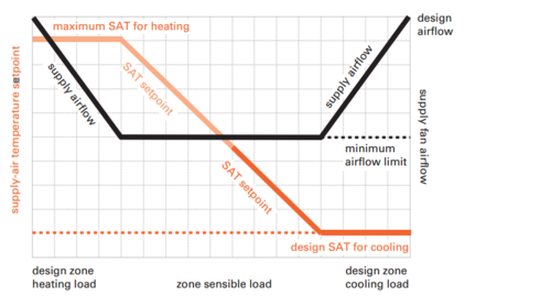
At maximum cooling load, the system supplies the minimum supply air temperature and maximum supply air flow. As the load decreases, the supply airflow decreases until it reaches a minimum value. At this point, the supply air temperature will begin to increase until the system switches into heating mode. As the heating load increases, the supply air temperature will continue to increase until it reaches a maximum value. At this point, the supply airflow will increase again until it reaches its maximum at the design heating load.
Each zone assigned to this system using this control strategy will be given its own set of coils. For example, if 10 zones are assigned to an individual Single Zone VAV system, 10 systems will be created, one per zone.
Fan control: There are three different methods that can be used to control the fan. The fan can be variable speed so it can operate at any speed within its range. The fan can operate at only two different speeds. The fan can also be set to it is variable volume when the system is in cooling mode but constant volume when the system is in heating mode.
Turndown ratio: This is a fraction of the minimum allowable supply airflow to the maximum supply airflow. The decreased airflow can be achieved by either closing a VAV damper or decreasing the airflow through the supply fan.
Maximum supply air temperature: This is the maximum limit for the supply air temperature.
Minimum supply air temperature: This is the minimum limit for the supply air temperature.
Enable fan static pressure modifier: This allows the fan static pressure to vary during the simulation.
Supply air temperature reset per main supply setpoint
This control strategy is only available for DOA systems. The conditioned outdoor air temperature from the DOA will be controlled to be equal to the main supply air temperature of the system it is associated with, even if the main system supply air temperature is being reset. For instance, if at a particular hour, the main system is being controlled to deliver 55 F air, the DOA will also be controlled to supply 55 F outdoor air.
Supply air temperature reset per mixed air condition
This control strategy is only available for DOA systems. The conditioned outdoor air temperature from the DOA will be controlled such that the mixed air temperature is equal to the main system supply air temperature. This is in an effort to prevent the main system coils from operating. For example, if the required SADB for a particular hour is 55 F, the system is 80% OA and the return air temperature is 75 F, the DOA should control the outdoor air to be conditioned to 50 F to cause the mixed air temperature to equal 55 F.
(% OA/100) * (T_OA) + (1 - (% OA/100)) * (T_RA) = T_MA
(0.8 * T_OA) + (0.2 * 75 F) = 55 F
T_OA = 50 F
Where % OA = percent of outdoor air
T_OA = outdoor air temperature after being conditioned by the DOA
T_RA = return air temperature
T_MA = mixed air temperature
Maximum Outdoor Air Temperature
This is the upper limit for the conditioned outdoor air temperature. If the calculated conditioned outdoor air temperature is higher than this value, the program will use this value.
Minimum Outdoor Air Temperature
This is the lower limit for the conditioned outdoor air temperature. If the calculated conditioned outdoor air temperature is lower than this value, the program will use this value.
Humidity
The humidity controller is used to control humidity at a certain point in the system. The humidity controller should be connected to a cooling coil. A humidity controller is not required.
|
| ||
|
|
|
Supply air humidity reset per maximum
The maximum humidity ratio at the location where this humidity controller is placed is controlled to a certain constant humidity ratio or variable humidity ratio as defined in either the constant or variable control setpoint fields.
Setpoint Control Type: This defines if the supply air humidity setpoint will be a constant value or a variable value.
Constant Control Setpoint: This is the supply air humidity setpoint if the setpoint is constant.
Variable Control Setpoint: This is the supply air humidity setpoint if the setpoint is variable.
Supply air humidity reset per single zone maximum
The humidity ratio is controlled to one particular zone on the system. The current humidity ratio in that zone is measured and the supply air humidity ratio is calculated to keep the zone humidity ratio at or below a setpoint value. Dehumidification may be necessary to maintain the humidity ratio below this value.
Control Zone: This will be the zone that the system will control the supply air humidity to. The control zones can only be selected in the project after zones have been assigned to the system. Note, in the project this field will be shown even before zones have been assigned but cannot be edited until after zones have been assigned to the system. By default, the first zone assigned to the system will be set as the control zone but any zone assigned to the system can be selected from this dropdown.
Supply air humidity reset per multizone maximum avg
The humidity ratio is controlled by multiple zones on the system. The current humidity ratio in those zones is measured and an average supply air humidity ratio is calculated to keep the zone humidity ratio between two setpoint values. Dehumidification or humidification may be necessary to maintain the humidity ratio between these values.
Minimum Humidity Ratio: The average room relative humidity ratio should remain above this value.
Maximum Humidity Ratio: The average room relative humidity ratio should remain below this value.
Supply air humidity reset per multizone maximum
The humidity ratio is controlled by multiple zones on the system. The current humidity ratio in those zones is measured and the supply air humidity ratio is calculated in order to keep all zones between two setpoint values. Dehumidification or humidification may be necessary to maintain the humidity ratio between these values.
Minimum Humidity Ratio: The room relative humidity ratio should remain above this value.
Maximum Humidity Ratio: The room relative humidity ratio should remain below this value.
Supply air humidity reset per mixed air max humidity
This control strategy is only available for DOA systems. The conditioned outdoor air humidity ratio from the DOA will be controlled such that the mixed air humidity ratio is low enough to serve the worst case room on the system. For example, if the required humidity ratio (w) for a particular hour is 60 gr/lb, the system is 80% OA and the return air humidity ratio is 90 gr/lb, the DOA should control the outdoor air to be conditioned to 52.5 gr/lb to cause the mixed air humidity ratio to equal 60 gr/lb.
(% OA/100) * (w_OA) + (1 - (% OA/100)) * (w_RA) = w_MA
(0.8 * w_OA) + (0.2 * 90 gr/lb) = 60 gr/lb
w_OA = 52.5 gr/lb
Where % OA = percent of outdoor air
w_OA = outdoor air humidity ratio after being conditioned by the DOA
w_RA = return air humidity ratio
w_MA = mixed air humidity ratio
Maximum Humidity Ratio
This is the upper limit for the conditioned outdoor air humidity ratio. If the calculated conditioned outdoor air humidity ratio is higher than this value, the program will use this value.
Minimum Humidity Ratio
This is the lower limit for the conditioned outdoor air humidity ratio. If the calculated conditioned outdoor air humidity ratio is lower than this value, the program will use this value.
Zone Level Equipment
If there are any zone level equipment included in the system, they will be listed in the Zone Level Equipment tab. As pieces of equipment are added or removed, the list in the tab will update. The equipment libraries can be selected here.
Component Name
This is the name of the specific component in the system and will match the tag name above the component in the system diagram. This name is editable.
Category
This is the library where this specific component is found.
Type
This is a subcategory in the library where this specific component is found.
Library Items
This is the actual library member that will be used to represent this component.
Zone Equipment Availability Manager
The Zone Equipment Availability Manager tab contains information on night purge, schedule, fan cycling, and optimum start for the zone level equipment.
Terminal Devices
The Terminal Devices tab contains properties on airflow and equipment in the terminal device. Each system is required to have one and only one terminal device. Terminal devices can be changed for different zones on the same system in the Configure Zone Equipment tab in the project.
|
|
| |
|
|
|
|
|
|
|
|
|
|
|
|
Diffuser (no properties)
The Diffuser represents a diffuser into a zone that has no VAV damper, fan, or coil.
CV Terminal Reheat
The Constant Volume with reheat terminal device is used in constant volume systems in order to reheat the supply air before it enters the zone.
Reheat Coil Type: This is the heating coil library sub category which also defines the energy type that is used to heat the coil.
Reheat Coil: This is the specific heating coil library that will be used as the heating coil.
Maximum Reheat Air Temperature: This is the maximum temperature to which the supply air can be heated by the reheat coil. If this field is left blank, there will be no upper limit to the supply air temperature.
VAV Terminal
The VAV Terminal is used to control the supply air of a VAV system using a VAV damper but has no coil or fan.
Damper Heating Action: There are three different options for how the supply airflow can be controlled when the system is in heating mode.
Normal: During heating mode the damper will always remain at the minimum position and the supply air temperature will be increased as the heating load increases. The equipment will be sized so the peak heating load can be satisfied at the minimum heating supply airflow and maximum heating supply air dry bulb.
Dual Maximum: During heating mode, the damper will remain at the minimum position and the supply air temperature will be increased as the heating load increases. Once the supply air temperature reaches a maximum, the VAV damper will start to open, increasing the supply airflow at the maximum supply air temperature. The maximum heating supply airflow will be less than the maximum cooling supply airflow. This control type is only used for hot water reheat coils.
Dual Maximum 100% in Heating: During heating mode, the damper will remain at the minimum position and the supply air temperature will be increased as the heating load increases. Once the supply air temperature reaches a maximum, the VAV damper will start to open, increasing the supply airflow at the maximum supply air temperature. The maximum heating supply airflow will be equal to the maximum cooling supply airflow. This control type is only used for hot water reheat coils.
Clg VAV min Type
The cooling VAV minimum can either be set to a constant value or the VAV minimum can vary. According to a schedule.
Clg VAV min
|
Default: 30% Clg Airflow
|
|
Typical Range: N/A
|
|
Min Max: 0 to infinity
|
|
Units: % Clg Airflow; cfm; cm3/s; m3/s; m3/hr
|
When the Clg VAV min type is set to constant, this is the minimum supply air flow rate for the VAV system in terms of a percent of the maximum design air flow rate or as an airflow rate value.
When the Clg VAV min type is set to variable, a schedule can be chosen in this field that defines the changing VAV minimum.
VAV w/Reheat
The VAV with reheat terminal device is used to control the supply air of a VAV system using a VAV damper. The terminal box also contains a reheat coil to heat supply air before it enters the space.
Clg VAV min type: The VAV with reheat terminal device is used to control the supply air of a VAV system using a VAV damper. The terminal box also contains a reheat coil to heat supply air before it enters the space.
Clg VAV min
|
Default: 30% Clg Airflow
|
|
Typical Range: N/A
|
|
Min Max: 0 to infinity
|
|
Units: % Clg Airflow; cfm; cm3/s; m3/s; m3/hr
|
When the Clg VAV min type is set to constant, this is the minimum supply air flow rate for the VAV system in terms of a percent of the maximum design air flow rate or as an airflow rate value.
When the Clg VAV min type is set to variable, a schedule can be chosen in this field that defines the changing VAV minimum.
Reheat coil type: This is the heating coil library sub category.
Reheat coil: This is the specific heating coil library that will be used as the heating coil.
Damper Heating Action: There are three different options for how the supply airflow can be controlled when the system is in heating mode.
● Normal: During heating mode the damper will always remain at the minimum position and the supply air temperature will be increased as the heating load increases. The equipment will be sized so the peak heating load can be satisfied at the minimum heating supply airflow and maximum heating supply air dry bulb.
● Dual Maximum: During heating mode, the damper will remain at the minimum position and the supply air temperature will be increased as the heating load increases. Once the supply air temperature reaches a maximum, the VAV damper will start to open, increasing the supply airflow at the maximum supply air temperature. The maximum heating supply airflow will be less than the maximum cooling supply airflow. This control type is only used for hot water reheat coils.
● Dual Maximum 100% in Heating: During heating mode, the damper will remain at the minimum position and the supply air temperature will be increased as the heating load increases. Once the supply air temperature reaches a maximum, the VAV damper will start to open, increasing the supply airflow at the maximum supply air temperature. The maximum heating supply airflow will be equal to the maximum cooling supply airflow. This control type is only used for hot water reheat coils.
Maximum Reheat Temperature
|
Default: blank
|
|
Typical Range: N/A
|
|
Min Max: 0 to infinity
|
|
Units: °F; °C
|
This is the maximum temperature the heating supply air is allowed to reach.
Htg VAV max
|
Default: Autosize
|
|
Typical Range: N/A
|
|
Min Max: -infinity to infinity
|
|
Units: % Clg Airflow; cfm/sq•ft (floor); (m3/s)/sq•m (floor); (m3/hr)/sq•m (floor)
|
This field is only used if the Damper Heating Action is set to “Dual Maximum Control”. This value indicates the maximum supply airflow during heating when the VAV damper increases from the minimum value as the heating load increases. This can be input as a percent of the total cooling supply airflow or as an air flow rate per floor area.
VAV Fan Assisted Reheat
The VAV with fan assisted reheat terminal box contains a VAV damper to control airflow into the space as well as a heating coil in series with a variable speed fan. The fan controls the amount of supply air entering the zone and is commonly found in UFAD systems.
Clg VAV min
|
Default: 30% Clg Airflow
|
|
Typical Range: N/A
|
|
Min Max: 0 to infinity
|
|
Units: % Clg Airflow; cfm; cm3/s; m3/s; m3/hr
|
This is the minimum supply air flow rate for the VAV system in terms of a percent of the maximum design air flow rate or as an airflow rate value.
Heating Coil Type: This is the heating coil library sub category.
Heating Coil: This is the specific heating coil library that will be used as the heating coil.
Fan Type: This is the fan library sub category.
Variable Volume Fan: This is the specific fan library that will be used as the fan in this system.
Parallel Fan Powered VAV
The parallel fan powered VAV boxes contain a VAV damper to control airflow into the zone as well as a heating coil in parallel with a constant volume fan that recirculates air from the zone. Only the recirculated air passes through the fan but both the recirculated and supply air passes through the heating coil. The air entering the zone is equal to the sum of the supply air and the recirculated air.
Clg VAV min
|
Default: 30% Clg Airflow
|
|
Typical Range: N/A
|
|
Min Max: 0 to infinity
|
|
Units: % Clg Airflow; cfm; cm3/s; m3/s; m3/hr
|
This is the minimum supply air flow rate for the VAV system in terms of a percent of the maximum design air flow rate or as an airflow rate value.
Heating Coil Type: This is the heating coil library sub category.
Heating Coil: This is the specific heating coil library that will be used as the heating coil.
Fan Type: This is the fan library sub category.
Constant Volume Fan: This is the specific fan library that will be used as the fan in this system.
Fan Flow Fraction
|
Default: Autosize
|
|
Typical Range: 0–1
|
|
Min Max: 0–1
|
|
Units: dimensionless
|
The secondary fan in the terminal box doesn’t always need to run. The fan flow fraction represents the ratio of the current supply airflow to the maximum design supply airflow. When the current flow fraction is above this value, the secondary fan will not run. When the fan flow fraction is below this value, the secondary fan will run. For example, a fan flow fraction of 1 means the secondary fan will run all the time. If the fan flow fraction is 0.7, the secondary fan will only operate when the supply airflow is at 70% or less than the design supply airflow.
Series Fan Powered VAV
The series fan powered VAV boxes contain a VAV damper to control airflow into the zone as well as a heating coil in series with a constant volume fan that recirculates air from the zone. Both the recirculated and supply air pass through the fan and the reheat coil. The air entering the zone is equal to the sum of the supply air and the recirculated air.
Clg VAV min
|
Default: 30% Clg Airflow
|
|
Typical Range: N/A
|
|
Min Max: 0 to infinity
|
|
Units: % Clg Airflow; cfm; cm3/s; m3/s; m3/hr
|
This is the minimum supply air flow rate for the VAV system in terms of a percent of the maximum design air flow rate or as an airflow rate value.
Heating Coil Type: This is the heating coil library sub category.
Heating Coil: This is the specific heating coil library that will be used as the heating coil.
Fan Type: This is the fan library sub category.
Constant Volume Fan: This is the specific fan library that will be used as the fan in this system.
Dual Duct CV (no properties)
The dual duct constant volume terminal device is only available in the Dual Duct system category. Dual duct systems have separate air paths for hot and cold air. These air streams are mixed in this terminal device in order to adequately condition the space. Different proportions of the hot and cold air may be mixed but the sum of the airflows will be constant.
Dual Duct VAV
The Dual Duct VAV terminal device is only available in the Dual Duct system category. Dual duct systems have separate air paths for hot and cold air. These air streams are mixed in this terminal device in order to adequately condition the space. Different proportions of the hot and cold air may be mixed and the total supply airflow may vary.
Clg VAV min
|
Default: 30% Clg Airflow
|
|
Typical Range: N/A
|
|
Min Max: 0 to infinity
|
|
Units: % Clg Airflow; cfm; cm3/s; m3/s; m3/hr
|
This is the minimum supply air flow rate for the VAV system in terms of a percent of the maximum design air flow rate or as an airflow rate value.
Four Pipe Induction
The Four Pipe Induction terminal device comes with a water cooling coil and water heating coil. Centrally conditioned air is forced through this terminal unit through a nozzle, inducing room air to flow over these terminal coils. The unit has two inlets and two outlets so the unit can do cooling and heating simultaneously. This terminal device is only available in the Chilled Beam and Induction category.
Induction Ratio
|
Default: blank
|
|
Typical Range: N/A
|
|
Min Max: 0 to infinity
|
|
Units: dimensionless
|
The induction ratio is the ratio of the induced airflow through the unit to the primary supply airflow rate.
Heating Coil Type: This is the heating coil library sub category.
Heating Coil: This is the specific heating coil library that will be used as the heating coil.
Cooling Coil Type: This is the cooling coil library sub category.
Cooling Coil: This is the specific cooling coil library that will be used as the cooling coil.
Chilled Beam (Active) and Chilled Beam (Passive)
The Chilled Beam terminal device is used to do sensible cooling on centrally conditioned and dehumidified supply air. This terminal device includes a cooling coil. The chilled beam can be set to active or passive in the terminal device properties. This terminal device is only available in the Chilled Beam and Induction category.
Chilled Beam Type: Either active or passive chilled beams can be modeled. An active chilled beam supplies air through the unit in order to induce room air to pass over the beam. A passive chilled beam however uses only natural convection to cool the air.
Number of Beams
|
Default: blank
|
|
Typical Range: N/A
|
|
Min Max: 0 to infinity
|
|
Units: dimensionless
|
This is the number of chilled beams in the zone. This can be autosized based on the design load of the zone.
Beam Length
|
Default: blank
|
|
Typical Range: N/A
|
|
Min Max: 0 to infinity
|
|
Units: ft; m
|
This is the length of each individual beam. This can also be autosized based on the design load in the zone.
Design Inlet Water Temperature
|
Default: blank
|
|
Typical Range: N/A
|
|
Min Max: 0 to infinity
|
|
Units: °F; °C
|
This is the inlet water temperature as it enters the chilled beam.
Design Outlet Water Temperature
|
Default: blank
|
|
Typical Range: N/A
|
|
Min Max: 0 to infinity
|
|
Units: °F; °C
|
This is the outlet water temperature as it leaves the chilled beam.
Coil Parameters
The advanced parameters can be used to define information to characterize the performance of the chilled beam using these equations.
Beam cooling output per unit length [W/m]
Coil heat transfer coefficient [W/(m2K)]
Room air mass flow rate across coil [kg/(m2s)]
Room air volumetric flow rate across coil per unit length [m3/(s•m)]
Where:
ΔT is the room air – water temperature difference (average water temperature is used) in degrees C.
ω is the water velocity in m/s.
qpr is the supply air flow rate per unit length [m3/(s•m)]
Coil Surface Area per Coil Length
|
Default: blank
|
|
Typical Range: N/A
|
|
Min Max: 0 to infinity
|
|
Units: m2/m
|
Coefficient in the above equations
Coefficient a
|
Default: blank
|
|
Typical Range: N/A
|
|
Min Max: 0 to infinity
|
|
Units: dimensionless
|
Coefficient in the above equations
Coefficient n1
|
Default: blank
|
|
Typical Range: N/A
|
|
Min Max: 0 to infinity
|
|
Units: dimensionless
|
Coefficient in the above equations
Coefficient n2
|
Default: blank
|
|
Typical Range: N/A
|
|
Min Max: 0 to infinity
|
|
Units: dimensionless
|
Coefficient in the above equations
Coefficient n3
|
Default: blank
|
|
Typical Range: N/A
|
|
Min Max: 0 to infinity
|
|
Units: dimensionless
|
Coefficient in the above equations
Coefficient a0
|
Default: blank
|
|
Typical Range: N/A
|
|
Min Max: 0 to infinity
|
|
Units: m2/M
|
This is the free area of the coil in plan view (for the air flow) per unit beam length.
Coefficient K1
|
Default: blank
|
|
Typical Range: N/A
|
|
Min Max: 0 to infinity
|
|
Units: dimensionless
|
Coefficient in the above equations
Coefficient n
|
Default: blank
|
|
Typical Range: N/A
|
|
Min Max: 0 to infinity
|
|
Units: dimensionless
|
Coefficient in the above equations
Induction Ratio
|
Default: blank
|
|
Typical Range: N/A
|
|
Min Max: 0 to 4
|
|
Units: dimensionless
|
Coefficient in the above equations. This value is sometimes known as the coefficient of conduction or Kin.
Leaving Pipe Inside Diameter
|
Default: blank
|
|
Typical Range: N/A
|
|
Min Max: 0 to infinity
|
|
Units: m
|
This is the inner diameter of the leaving pipe.
Zone Sizing
The Zone Sizing tab contains information for zone level sizing properties.
Cooling Supply Air Dry Bulb
|
Default: 55°F
|
|
Typical Range: N/A
|
|
Min Max: -infinity to infinity
|
|
Units: °F, °C
|
This is the temperature of the supply air as it enters the zone in cooling mode. Note: This temperature field is only used if there is a zone level cooling coil or a terminal box cooling coil. Otherwise this field will be ignored. Additionally, if the “Apply System Cooling SAT to Zone” field in the Sizing Properties tab is set to “yes”, this field will also be ignored and the “Supply Air Dry Bulb Cooling” temperature on the Sizing Properties tab will be used to size zone level cooling equipment. If the system level cooling equipment and zone level cooling equipment are sized to the same temperature, unmet hours could result.
Heating Supply Air Dry Bulb
|
Default: 125°F
|
|
Typical Range: N/A
|
|
Min Max: -infinity to infinity
|
|
Units: °F, °C
|
This is the temperature of the supply air as it enters the zone in heating mode. Note: This temperature field is only used if there is a zone level heating coil or a terminal box heating coil. Otherwise this field will be ignored. Additionally, if the “Apply System Heating SAT to Zone” field in the Sizing Properties tab is set to “yes”, this field will also be ignored and the “Supply Air Dry Bulb Heating” temperature on the Sizing Properties tab will be used to size zone level heating equipment. If the system level heating equipment and zone level heating equipment are sized to the same temperature, unmet hours could result.
Outdoor Air Control
The Outdoor Air Control tab contains property information for conditioning the outside air including flow rates and economizer information. Note, dedicated outside air units have their own category in the system library where their properties are defined.
|
| ||
|
|
Minimum outdoor air flow
|
Default: autosize
|
|
Typical Range: N/A
|
|
Min Max: -infinity to infinity
|
|
Units: cfm
|
The minimum outdoor air flow rate to the system can be autosized or input as a specific value.
Economizer
Economizer control type
● No Economizer – There is no economizer control in the system.
● Fixed Dry Bulb – The economizer will bring in the minimum outdoor air unless the outdoor air dry bulb is less than the specified economizer dry bulb limit.
● Fixed Enthalpy – The economizer will bring in the minimum outdoor air unless the outdoor air enthalpy is less than the specified economizer enthalpy limit.
● Differential Dry Bulb – The economizer will bring in the minimum outdoor air unless the outdoor air dry bulb is less than the return air dry bulb temperature.
● Differential Enthalpy – The economizer will bring in the minimum outdoor air unless the outdoor air enthalpy is less than the return air enthalpy.
● Fixed Enthalpy – The economizer will bring in the minimum outdoor air unless the outdoor humidity ratio is less than the calculated humidity ratio limit. The humidity ratio limit is calculated based on the dry bulb temperature of the outdoor air and a quadratic/cubic curve.
● Differential Dry Bulb and Enthalpy – The economizer will bring in the minimum outdoor air unless the both the outdoor air dry bulb and outdoor air enthalpy are respectively lower than the return air dry bulb and return air enthalpy.
Economizer Outdoor Air Control
● Modulated Outdoor Airflow – This will control the economizer to increase the outdoor airflow until the mixed air temperature setpoint is met.
● Minimum Flow - Bypass – The economizer will bring in the minimum outdoor air unless high humidity control is used. In this case, the outdoor air flow rate will be equal to the product of the maximum outdoor flow rate and the outdoor air ratio – high humidity. These inputs are found in the Humidity Control section.
Economizer Maximum DB Temperature
|
Default: blank
|
|
Typical Range: N/A
|
|
Min Max: -infinity to infinity
|
|
Units: °F, °C
|
The economizer won’t run unless the outdoor air dry bulb is below this temperature if the Economizer Control Type is set to Fixed Dry Bulb. If this field is left blank, the economizer can run at any outdoor dry bulb temperature.
Economizer Maximum Enthalpy
|
Default: blank
|
|
Typical Range: N/A
|
|
Min Max: -infinity to infinity
|
|
Units: Btu/lb; J/Kg
|
The economizer won’t run unless the outdoor air enthalpy is below this value if the Economizer Control Type is set to Fixed Enthalpy. If this field is left blank, the economizer can run at any outdoor air enthalpy.
Economizer Maximum Dew Point Temperature
|
Default: blank
|
|
Typical Range: N/A
|
|
Min Max: -infinity to infinity
|
|
Units: °F, °C
|
The economizer won’t run unless the outdoor air dew point temperature is below this temperature if the Economizer Control Type is set to Fixed Dew Point And Dry Bulb. If this field is left blank, the economizer can run at any outdoor air dew point temperature.
Economizer Minimum DB Temperature
|
Default: blank
|
|
Typical Range: N/A
|
|
Min Max: -infinity to infinity
|
|
Units: °F, °C
|
The economizer won’t run if the outdoor air dry bulb temperature is below this temperature. If this field is left blank, there is no low dry bulb temperature limit to economizer operation.
Lockout Type
Lockout is used for packaged units with DX coils.
None: The economizer will not be locked out.
● Economizer Lockout - Heating – The economizer will be locked out if the unit is in heating mode. The economizer will only run in heating if it can meet the entire heating load.
● Economizer Lockout – Cooling and Heating – The economizer will be locked out both when the system is in heating mode and when the system is in cooling mode and the compressor is operating. The economizer dampers will only open if economizing can meet either the entire heating load if the system is in heating or the entire cooling load if the system is in cooling.
Enable Time of Day Economizer
Designates whether or not to use a time of day economizer schedule.
Time of Day Economizer
This is a schedule from the library that controls whether the economizer can operate based on the time of day. If the schedule reads 0, the economizer cannot operate during that time. If the schedule reads something greater than 0, the economizer can operate.
System-Level Ventilation Overrides
Enable Ventilation Overrides
● None – There are no system level ventilation overrides applied
● Maximum Fraction of Outdoor Air Schedule – This is used to define the maximum outdoor air based on a schedule.
● Minimum Outdoor Air fraction of Design Schedule – This is used to define the minimum outside air as a fraction of the total design airflow based on a schedule.
● Minimum Outdoor Air Modifier Schedule – This is used to define the minimum outside air as a fraction of the design minimum outdoor air flow rate based on a schedule.
Maximum Fraction of Outdoor Air Schedule
This is a schedule from the library that is a direct multiplier on the total design air flow rate to define the maximum amount of outdoor air.
Minimum Outdoor Air Fraction of Design Schedule
This is a schedule from the library that is a direct multiplier on the total design air flow rate to define the minimum amount of outdoor air.
Minimum Outdoor Air Modifier Schedule
This is a schedule from the library that is a direct multiplier on the minimum outdoor air flow rate. If this field is left blank, the outdoor air flow will vary according to the Minimum Limit Type.
Ventilation Reset
Ventilation Reset Flag
Setting this field to Yes enables the rest of the fields in this section. This allows different ventilation calculation methods to be used, including ASHRAE 62.1 and Demand Control Ventilation.
DCV
If this field is set to Yes, the system will be able to vary the amount of ventilation to the zones using demand control ventilation. Demand Control Ventilation varies the ventilation to the system based on the people in the system zones. Fewer people require less ventilation, so if the people schedule shows less than the maximum number of people, the maximum outdoor airflow is not required.
If this field is set to No, the system will not be able to use demand control ventilation to vary the ventilation airflow and minimum ventilation requirement will remain constant.
System Outdoor Air Method
● Zone Sum – Sum of Outdoor Air – This method sums the ventilation requirements for all the zones on the system and uses that value for the system level ventilation.
● VRP – ASHRAE 62.1 – This ventilation rate procedure method uses the multizone calculations described in ASHRAE Standard 62.1 to calculate the system level ventilation based on the people and area based ventilation requirements of each zone.
● Proportional Control – Design Occupancy – This method can be used for single zone systems to calculate the ventilation airflow required to vary in proportion to the percent of CO2 using the procedure described in ASHRAE Standard 62.1 based on the design occupancy.
● Proportional Control – Actual Occupancy – This method can be used for single zone systems to calculate the ventilation airflow required to vary in proportion to the percent of CO2 using the procedure described in ASHRAE Standard 62.1 based on the actual occupancy.
● IAQP – This indoor air quality procedure method calculates the ventilation airflow required to keep CO2 levels in the zones below a set point value using the procedure described in ASHRAE Standard 62.1.
Maximum Outdoor Air
|
Default: blank
|
|
Typical Range: N/A
|
|
Min Max: 0–1
|
|
Units: dimensionless
|
The zone maximum outdoor air fraction represents the maximum fraction of the total supply air that should be ventilation. If the ventilation requirement is higher than the maximum outdoor air fraction, the return airflow will be increased so both the ventilation cfm requirement and the maximum outdoor air fraction are met. This also takes into account unused outdoor air in the return air stream.
Maximum Vent Z Ratio
|
Default: blank
|
|
Typical Range: N/A
|
|
Min Max: 0–1
|
|
Units: dimensionless
|
When modeling ASHRAE 62.1, the Outdoor Air Fraction in discharge air is calculated for each room, and the “critical zone” in turn sets the percentage of outside air for the entire system. The OA fraction (or Z ratio) for the critical zone or zones can be reduced by increasing the VAV minimum flow for that room. The Z ratio in the program is the same as Zd in the ASHRAE standard.
The “ASHRAE STD62 Max Vent (Z) Ratio Allowed” should only be input after viewing the ASHRAE Standard 62.1 report. Based on the substantial majority of the OA Fractions listed for the rooms on a system, you may then decide to input a maximum OA Fraction, or Max Vent (Z) Ratio, for the entire system. This replaces the need to manually increase the VAV Minimum Flow for each successive critical zone, an iterative process that can be time-consuming.
If a system level Max Vent (Z) Ratio is input to automatically increase the VAV minimum flows of all the rooms that fall below this OA Fraction, care must be taken to avoid raising the VAV minimums above the optimal point in terms of energy consumption. While increasing the VAV minimum flows will decrease the outside air intake flow required, it will also increase both the amount of reheat required and the fan energy consumption.
The “ASHRAE STD62 Max Vent (Z) Ratio Allowed” input is the maximum percentage allowed for the ventilation fraction of the critical zone (Z). During the System Simulation, the VAV minimum flow is increased to prevent the Z ratio from exceeding this limit.
Outdoor Carbon Dioxide Setpoint Control Type
When demand control ventilation is used with proportional control (either based on design occupancy or actual occupancy), the outdoor CO2 setpoint needs to be defined. The setpoint can be controlled either as a variable control or a constant control.
Constant Control Setpoint
When the constant control setpoint is used, the intake airflow is adjusted to maintain the indoor CO2 concentration in the space as defined in this field.
Variable Control Setpoint
The variable control setpoint will vary the outdoor air flow proportionally between the minimum and maximum ventilation airflows by taking a CO2 sample from the space.
Humidity Control
High Humidity Control
The high humidity control can be turned on or off by selecting yes or no respectively from this dropdown. This is used in conjunction with the Minimum Flow with Bypass option in the Economizer Control Action Type control.
Control Zone
This is the zone where the humidistat is located. This can only be defined in the project after the zones have been assigned to the system. Note, in the project this field will be shown even before zones have been assigned but cannot be edited until after zones have been assigned to the system. By default, the first zone assigned to the system will be set as the control zone but any zone assigned to the system can be selected from this dropdown.
Outdoor Air Ratio – High Humidity
|
Default: blank
|
|
Typical Range: N/A
|
|
Min Max: 0–1
|
|
Units: dimensionless
|
This is the ratio of the current outdoor air flow rate to the maximum outdoor air flow rate. This is used with the high humidity control and the Minimum Flow with Bypass option in the Economizer Control Action Type control.
Control Zone Humidity based on Outdoor Air
When this control is set to No, the high humidity control will dehumidify whenever there is a moisture load in the zone. When this control is set to Yes, the high humidity control will dehumidify when there is a moisture load in the zone and the indoor humidity ratio is higher than the outdoor humidity ratio.
Heat Recovery Integrated with Economizer
Heat Recovery Control
This controller is used to determine whether a heat recovery device will be used or bypassed when the system is in economizer mode.
● None – There is no heat recovery device for the system.
● Heat Recovery Bypass – Economizer – This option forces all of the outside air to bypass the heat recovery device whenever the system is in economizer mode.
● Heat Recovery Bypass – Outdoor Air – This option forces all of the outside air to bypass the heat recovery device whenever the outdoor airflow is above the minimum outdoor air flow. If at the minimum outdoor airflow, the system heating coil turns on, the energy recovery device will turn on as well and the outdoor airflow will no longer be bypassed.
CO2
When the system outdoor air method field on the outdoor air control tab is set to VRP – ASHRAE 62.1, Proportional Control – Design Occupancy, Proportional Control – Actual Occupancy, or IAQP, this tab in the properties becomes available. A CO2 sensor also appears in the space. This tab allows you to define the CO2 setpoint that will be used to control the ventilation to the space.
Carbon Dioxide Setpoint Control Type
The CO2 setpoint can be either constant or variable. A constant setpoint uses a single ppm value of CO2 in the space to control the ventilation. A variable setpoint is allowed to change throughout the day to use different ppm values of CO2.
Constant Control Setpoint
If the Carbon Dioxide Setpoint Control Type is set to constant, this field will be available to define the parts per million CO2 allowed in the space.
Variable Setpoint
If the Carbon Dioxide Setpoint Control Type is set to variable, this field will be available to define the parts per million CO2 allowed in the space based on a schedule that changes throughout the day.