Systems Library
The System Library is where you can create a custom system to be used in an alternative. The System can be created new or can be copied from an existing system and edited. The components that are available to be applied to a system are in the component selection section.
*Incomplete systems can be saved, but cannot be selected in an actual file.
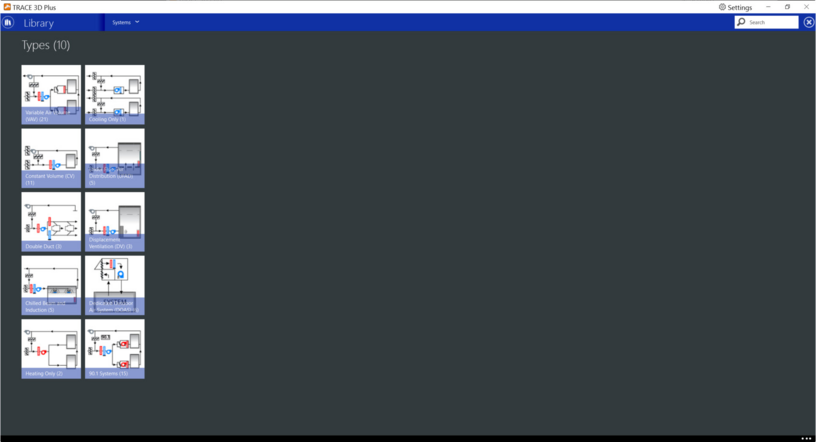
System Categories Screen
The System Categories Screen shows the list of System Categories and the number of Systems in the library for each system. The number includes both the standard libraries and custom libraries. You can also navigate to a different library using the System dropdown. Additionally, you can search for a specific library by name in the Search Library Field.
After a system category has been selected, the list of all the systems in that category will appear. This list contains both the standard systems, and user created custom system libraries categorized into folders. Any system can be selected to view however only the custom systems can be edited. Standard systems can be copied and the copy can be edited.
The user can also create a new custom system library member by clicking the Add Item button or create a new folder by clicking the Add Group button.
Add Group
This button is used to create a new folder within the System Category. For example, if a number of different custom system libraries are used for the same project, they can be organized together in one group folder in order to find them more easily.
Add Item
This button is used to create a new system library in the current system category.
Library Dropdown
The Library dropdown allows the user to navigate to a different library such as the equipment library or materials library.
Systems Category Dropdown
The systems category dropdown allows the user to navigate to a different system category for example to the 90.1 Systems category or the Variable Air Volume (VAV) category.
Search Library
The search window allows the user to search for a specific library member by name.
Patterns Screen
The first step in creating a new system library is to choose an air path pattern. The available air paths for the selected system category will be listed. System components will be added to the air path after the pattern is selected.
Below is a table that shows which patterns are available for each system category:
|
System
|
VAV
|
CV
|
Double Duct
|
Chilled Beam and Induction
|
Cooling Only
|
Heating Only
|
UFAD
|
DV
|
DOA
|
90.1
|
|
Single Duct
|
x
|
x
|
|
x
|
x
|
x
|
|
|
|
x
|
|
Single Duct w/RA Bypass
|
x
|
x
|
|
x
|
x
|
x
|
|
|
|
|
|
UFAD
|
|
|
|
x
|
|
|
x
|
|
|
|
|
UFAD w/ RA Bypass
|
|
|
|
x
|
|
|
x
|
|
|
|
|
DV
|
|
|
|
x
|
|
|
|
x
|
|
|
|
DV w/RA Bypass
|
|
|
|
x
|
|
|
|
x
|
|
|
|
Dual Duct
|
|
|
x
|
|
|
|
|
|
|
|
|
90.1 Zone Level System
|
|
|
|
|
|
|
|
|
|
x
|
|
Variable Volume Zone Level System
|
x
|
|
|
|
|
|
|
|
|
|
|
Constant Volume Zone Level System
|
|
x
|
|
|
|
|
|
|
|
|
|
Variable Refrigerant Flow
|
x
|
|
|
|
|
|
|
|
|
|
|
Cooling Only Zone Level Systems
|
|
|
|
|
x
|
|
|
|
|
|
|
Heating Only
|
|
|
|
|
|
x
|
|
|
|
|
|
DOA to Single Systems
|
|
|
|
|
|
|
x
|
|
x
|
|
|
DOA to Multiple Systems
|
|
|
|
|
|
|
|
|
x
|
|
|
DOA to Zone
|
|
|
|
|
|
|
|
|
x
|
|
|
Mechanical Ventilation Only System
|
|
|
|
|
|
|
|
|
x
|
|
|
| |||
|
| |||
|
| |||
|
|
Single Duct
The single duct pattern is available for the VAV, CV, Chilled Beam and Induction, Cooling Only, Heating Only, and 90.1 system categories. The single duct pattern allows for a single stream of air to be delivered to the zones assigned to the system.
Coils and fans will be at the system level and one set of coils and fans will serve all zones assigned to the system.
90.1 Single Duct with RA Bypass
The single duct with RA bypass pattern is available for the VAV, CV, Chilled Beam and Induction, Cooling Only,and Heating Only system categories.
The single duct with RA bypass pattern is typically used to bypass return air around the main cooling coil. This allows the cooling coil to over cool the air for dehumidification and reheat it using the bypassed return air.
Coils and fans will be at the system level and one set of coils and fans will serve all zones assigned to the system.
UFAD
The UFAD pattern is available only for the UFAD and Chilled Beam and Induction system types. This pattern configuration allows air to be supplied from an under-floor plenum instead of from the ceiling. Coils and supply fans will be placed in the underfloor plenum.
Coils and fans will be at the system level and one set of coils and fans will serve all zones assigned to the system.
UFAD with RA Bypass
The UFAD with RA Bypass pattern is available only for the UFAD and Chilled Beam and Induction system types. This pattern configuration allows air to be supplied from an under-floor plenum instead of from the ceiling. Coils and supply fans will be placed in the underfloor plenum.
Return air is bypassed around the main cooling coil. This allows the cooling coil to overcool the air for dehumidification and reheat it using the return air.
Coils and fans will be at the system level and one set of coils and fans will serve all zones assigned to the system.
DV
The DV pattern is available only for the DV and Chilled Beam and Induction system types. This pattern configuration allows air to be supplied through diffusers near the floor of the zone instead of the ceiling. Coils and supply fans will be placed in the underfloor plenum.
Coils and fans will be at the system level and one set of coils and fans will serve all zones assigned to the system.
DV with RA Bypass
The DV with RA Bypass pattern is available only for the DV and Chilled Beam and Induction system types. This pattern configuration allows air to be supplied through diffusers near the floor of the zone instead of the ceiling. Coils and supply fans will be placed in the underfloor plenum.
Return air is bypassed around the main cooling coil. This allows the cooling coil to overcool the air for dehumidification and reheat it using the return air.
Coils and fans will be at the system level and one set of coils and fans will serve all zones assigned to the system.
Dual Duct
The Dual Duct pattern is available only for the Dual Duct system category. This pattern is similar to the Single Duct pattern but with an additional parallel air path. The main supply air path splits into a cold deck and hot deck. The cold deck flows through the cooling coil and the hot deck flows through the heating coil. The two paths remix in the zone to achieve the desired supply air temperature.
Uniformly mixed return air is drawn from a common return air plenum.
Coils and fans will be at the system level and one set of coils and fans will serve all zones assigned to the system.
90.1 Zone Level System
The 90.1 Zone Level System is only available for the 90.1 system category. The pattern is used for creating 90.1 systems with zone/room level equipment.
When creating a zone level system, only Zone Level Equipment will be available. The zone level equipment library will define the coils, fans, and controls for the system. There will be no air path displayed on the system diagram and there will be no system level components, terminal devices or controls available to add to the system. The user will only need to select the zone level equipment and place it in the demand box to create the system library.
Variable Volume Zone Level System
The Variable Volume Zone Level System is only available for the VAV system category. This pattern is used to create systems with zone level VAV equipment. The zone level equipment available for this pattern is:
When creating a zone level system, only Zone Level Equipment will be available. The zone level equipment library will define the coils, fans, and controls for the system. There will be no air path displayed on the system diagram and there will be no system level components, terminal devices or controls available to add to the system. The user will only need to select the zone level equipment and place it in the demand box to create the system library.
Constant Volume Zone Level System
The Constant Volume Zone Level System is only available for the CV system category. This pattern is used to create systems with zone level CV equipment. The zone level equipment available for this pattern is:
When creating a zone level system, only Zone Level Equipment will be available. The zone level equipment library will define the coils, fans, and controls for the system. There will be no air path displayed on the system diagram and there will be no system level components, terminal devices or controls available to add to the system. The user will only need to select the zone level equipment and place it in the demand box to create the system library.
Variable Refrigerant Flow
The Variable Refrigerant Flow pattern is only available for the VAV system category. This pattern is used to create a variable refrigerant flow system. The zone level equipment available for this pattern is:
When creating a zone level system, only Zone Level Equipment will be available. The zone level equipment library will define the coils, fans, and controls for the system. There will be no air path displayed on the system diagram and there will be no system level components, terminal devices or controls available to add to the system. The user will only need to select the zone level equipment and place it in the demand box to create the system library.
Cooling Only Zone Level System
The Cooling Only Zone Level System pattern is only available for the Cooling Only system category. This pattern is used to create cooling only systems with zone level equipment. The zone level equipment available or this system is:
|
Window Air Conditioner
|
Evaporative Cooler Unit
|
Unit Ventilator (Cooling Only)
|
Variable Refrigerant Flow
|
When creating a zone level system, only Zone Level Equipment will be available. The zone level equipment library will define the coils, fans, and controls for the system. There will be no air path displayed on the system diagram and there will be no system level components, terminal devices or controls available to add to the system. The user will only need to select the zone level equipment and place it in the demand box to create the system library.
Heating Only
The Heating Only pattern is only available for the Heating Only system category. This pattern is used to create heating only systems with zone level equipment. The zone level equipment available for this system is:
|
Wall Cover
|
Radiant Heat
|
Unit Heater Heating Only
|
Unit Ventilator Heating Only
|
|
Variable Refrigerant Flow
(Heating Mode)
|
Ceiling Radiant Panel (Heating Only)
|
Infloor Radiant Panel (Heating Only)
|
|
The DOA patterns are used to create Dedicated Outdoor Air systems to condition outside air. The DOA to Single System pattern allows the user to create a DOA that will be assigned to a system that has system level equipment.
DOA to Multiple Systems
The DOA patterns are used to create Dedicated Outdoor Air systems to condition outside air. The DOA to Multiple Systems is used to create a DOA system that will be assigned to multiple zone level systems. This pattern is only available to be assigned to zone level fan coil and WSHP systems. This is a current limitation of EnergyPlus™.
DOA to Zone
The DOA patters are used to create Dedicated Outdoor Air systems to condition outside air. The DOA to Zone pattern is used to create DOA systems that will be assigned system that have zone level equipment except zone level fan coil and WSHP systems. These systems should use the DOA to Multiple Systems pattern.
Ventilation Only System
The Ventilation Only System is used for 100% OA systems in place of a standard system.
Systems List
There are 10 system categories. Each system category contains standard libraries but custom libraries can also be added to each category.
|
|
|
|
|
|
|
|
|
|
|
|
|
|
|
Variable Air Volume (VAV)
Each system type contains description of the system and its components.
|
|
|
|
|
|
|
|
Changeover-Bypass VAV
This system has a central air handler with integral heating and cooling coils that can supply either heated or cooled supply air to one or more rooms. The volume supplied to each zone is individually regulated by a zone VAV damper. Each VAV damper is linked to a zone thermostat sensor, thus enabling the occupants to choose their own local space temperature. Treated air is supplied to the zone VAV dampers via a network of low velocity ductwork supplied from a built-up air handling unit or a packaged rooftop unit. This central unit delivers a constant volume of air but is sized according to the block (coincident) cooling load. Any air that is not needed to heat or cool the rooms is simply returned back to the air handling unit via a system-level bypass loop. Each room VAV damper communicates with the main AHU as to whether the room requires hot or cold air to satisfy the room setpoint temperature.
Priority Control Mode
The operation of the VAV dampers in conjunction with the primary cooling and heating coils is determined by the Operating Mode in the changeover-bypass VAV equipment library. If Cooling Priority is selected, the system operates to meet the cooling load if any zone served by this system (air loop) requires cooling. If no zones require cooling, then the system operates in heating mode if needed. If Heating Priority is selected, the system operates to meet the heating load if any zone requires heating. If no zones require heating, then the system operates in cooling mode if needed. If Highest Mode Priority is selected, the system operates based on the maximum number of zones requiring either heating or cooling. If the number of zones requiring cooling is greater than the number of zones requiring heating, then the system operates in cooling mode. If the number of zones requiring heating is greater than the number of zones requiring cooling, then the system operates in heating mode. If the number of zones requiring cooling equals the number of zones requiring heating, then the largest combined load (i.e., the sum of the cooling loads for zones requiring cooling compared to the sum of the heating loads for zones that require heating) sets the cooling or heating operating mode for the system during that simulation time step. The operation of the individual room VAV dampers depends on the Air Terminal device chosen.
Deadband Mode
If none of the rooms are in either cooling or heating mode, then both the cooling and heating coils are deactivated, and the fan runs per the field “System Air Flow Rate When No Cooling or Heating is Needed. This is written behind the scenes and is autosized based on the system loads. This field is only used when the unitary system’s supply air fan cycling mode is specified as continuous fan operation. If the system’s supply air fan cycling mode is specified as continuous fan operation and this value is set to zero or the field is left blank, then the model assumes that the system air flow rate when no heating/cooling is needed is equal to the system air flow rate when the coils were last operating (for cooling operation or heating operation).
Real-life Application Considerations
This system is best suited to applications that require either heating or cooling but not both since at any given time the air handling unit must supply either warm or cool air. For isolated rooms that may occasionally require heating when the rest of the system needs cooling, electric or hot water reheat coils or baseboards can be provided to maintain comfort conditions. To satisfy minimum ventilation requirements, a room VAV minimum supply air setting can be defined to guarantee a minimum supply airflow into the room even if there is no demand for heating or cooling.
Changeover-Bypass VAV with Local Heat
Notice that in this configuration, the VAV boxes have no reheat coil, just a damper. The user could easily switch out the baseboard with a floor or ceiling radiant panel in the zone equipment tab of the systems section in the project.
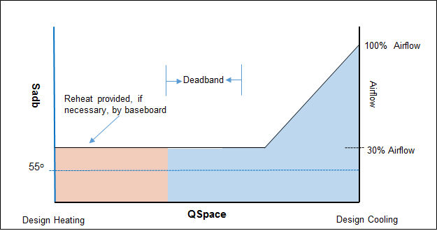
Cooling Mode Operation
If the AHU is in cooling mode, the VAV damper opens as needed in each room to provide sensible cooling to those room(s); however, with the AHU in cooling mode, the room(s) needing heat or in the deadband will receive cold supply air equal to the VAV minimum setting. See figure below. If this cold minimum supply airflow causes the space temperature to fall below a room’s heating thermostat, that room’s baseboard unit will activate to meet this “reheat” load.
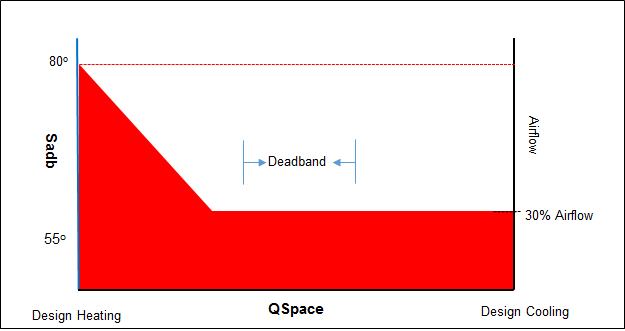
Heating Mode Operation
If the majority of rooms call for heating, the rooms are first served by their VAV box which will increase the heated supply air flow rate as needed to meet higher space heating loads. See figure below. If however, this heated supply air is inadequate to meet an individual room’s heating thermostat setpoint, the baseboard is activated to meet this remaining load. Any rooms that do not require heating will still receive heated supply airflow equal to their VAV minimum airflow setting and could temporarily lose control of their space temperature.
Changeover-Bypass VAV with Reheat
Notice that in the above configuration, the VAV boxes include a reheat coil as the only source of heating, and the damper heating action is set to Dual Maximum.
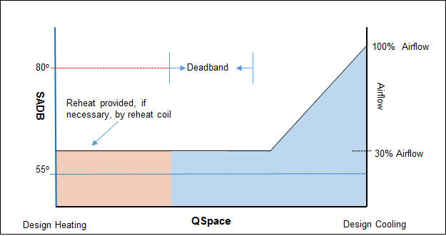
Cooling Mode Operation
If the AHU is in cooling mode, the VAV damper opens as needed in each zone to provide sensible cooling to those zone(s); however, with the AHU in cooling mode, the zone(s) needing heat or in the deadband will receive cold supply air equal to the VAV minimum setting. See figure below. If this cold minimum supply airflow causes the space temperature to fall below a room’s heating thermostat, that room’s reheat coil will activate to meet this “reheat” load.
Heating Mode Operation
If the majority of rooms call for heating, the rooms are first served by their VAV box which will increase the heated supply air flow rate as needed to meet higher space heating loads. See figure below. If additional heat is required (beyond what the terminal unit can provide with its damper fully open), then the reheat coil is modulated as needed to meet the additional heating load. Any rooms that do not require heating will still receive heated supply airflow equal to their VAV minimum airflow setting and could temporarily lose control of their space temperature.

Fan Powered VAV
Parallel Fan Powered VAV
The design is block air and block cooling capacity. This system is composed of a central, variable volume fan located on the cold deck that supplies cool air to each zone’s fan-powered VAV box. The return side of the fan powered box is said to be on the runaround deck since it draws plenum air from above the room served by the fan-powered box. The cooling supply fan is variable volume and will modulate in proportion to the sum of the cold deck airflows.
System Simulation
For non-mixing situations, the sequence of events is as follows. When the room drift temperature has risen above the room cooling thermostat, the cold deck side of the room mixing box is opened. The resulting room airflow is proportional to the room's design cooling load. When the room drift temperature drops below the room heating thermostat, only the return air side of the room mixing box opens and the unit fan is activated. The heating coil is activated within the fan-powered unit if the runaround air is unable to maintain the space above the heating thermostat setpoint. The unit fan is on for the portion of the hour it takes to bring up or maintain the room at the heating thermostat setpoint. When the room drift temperature lies within the dead band region, both the return air and the cold deck sides of the room mixing box are closed and no supply air is admitted to the space.
Mixing situations can occur in a room mixing box only when a reheat minimum airflow has been specified. A minimum stop defines the minimum amount of cold deck airflow that must be delivered to each space. As long as the room drift temperature stays above the room heating thermostat, no mixing takes place and the mixing box supplies air only from the cold deck. If, however, the room drift temperature falls below the heating thermostat settings, the runaround deck also opens such that the mixture of the warm and cool airflows controls the room temperature to the heating thermostat. Thus, as long as the room drift temperature remains in the dead band region, the room cold deck airflow will equal the room reheat minimum setting.
Note that shutting off mechanical cooling does not shut off the cooling supply fan. If the fan schedule reads 1% or greater, the cooling supply fan will modulate accordingly, supplying untreated return/outside air to the cold deck side of the mixing boxes that are open.
System Options
1. The value of minimum outside air nominally follows the outside air schedule. The amount of outside air introduced into the ROA deck may be greater than the ventilation minimum if an outside air economizer or nighttime purge is activated this hour.
In addition, the amount of outside air brought into a particular room is a function of how much cold deck air is needed by the room. If, for example, the drift temperature is below the cooling thermostat, the cold deck is closed and no outside air can be admitted (unless a reheat minimum has been specified). When the drift temperature is above the cooling thermostat, a proportional amount of outside air is admitted into the space.
2. If the main cooling fan is scheduled at zero percent for a particular hour, no ventilation airflow can be delivered to any of the rooms.
3. Supply air temperature reset can be defined using the temperature control in the controls tab of the system properties.
4. A reheat minimum will determine the minimum amount of cold deck air that is delivered into the space each hour.
Application Notes:
● While supply air temperature reset control of the cold deck can save mechanical cooling energy, the room humidity may be higher and the central VAV fan may consume more energy.
● Humidity compensated controls can be implemented by using the humidity controller on the controls tab of the system properties to modify the default settings. By using the option supply air reset per maximum, for example, whenever a room relative humidity is greater than the design room relative humidity, the room's VAV dampers will continue to open until the room relative humidity is lowered to the design room relative humidity.
Alternatively, by specifying the option supply air reset per multizone maximum avg, whenever the return air relative humidity is greater than the design system relative humidity (which is the average of the design room relative humidities for the zones served by the system), supply air reset controls are deactivated and the main cooling coil leaving air temperature is depressed to its design value for that hour.
Series Fan-Powered VAV
The design is block air and block cooling capacity. The system is composed of a central VAV fan located on the cold deck which supplies cold air to series fan-powered (FP) boxes located in each room. Air from the central VAV fan is mixed with plenum air at the FP unit. The FP unit delivers air to the space at a constant volume. If heat is required in the space, a reheat coil located at the terminus of the FP box will activate to meet the extra heating load.
System Simulation
A constant volume of air is delivered to each room as long as both the main cooling and main heating fans are scheduled on. Once the drift temperature is known for all rooms this hour, the program calculates the supply air temperature and the proportions of cold and runaround deck air required by each room. When the room drift temperature has risen above the room cooling thermostat, cool air from the cold deck side of the FP unit opens and mixes with warm air from the runaround deck side of the FP unit such that the mixture temperature is sufficient to meet the cooling load. When the room drift temperature drops below the room heating thermostat, the reheat coil in the FP unit is energized, heating the supply air to a temperature which will maintain the space at the heating thermostat temperature. When the drift temperature is in the dead band, only untreated plenum air is admitted to the space.
System Options
1. The value of minimum room outside air airflow nominally follows the outside air schedule. The amount of outside air brought into the cold deck side of the room mixing box may be greater than the minimum if an outside air economizer or nighttime purge is activated this hour.
The quantity of outside air brought into the cold deck side of the mixing box may be less than the minimum if the cooling load for an individual room calls for cooling airflow less than the minimum ventilation airflow. In either the heating-only mode or in the deadband temperature range, no outside air can be delivered to the room (unless a reheat minimum has been input).
Single Zone Variable Air Volume
This system consists of a variable volume fan, a DX cooling coil and a heating coil (usually electric resistance heat) and serves a single zone. The coils and fan are therefore located at the zone level, meaning that a separate Single Zone VAV (SZVAV) unit will be created for each zone attached to that system type. If a given zone is comprised of several rooms, this system is typically controlled by a single thermostat located in one of the rooms. This means that all the rooms get the same supply airflow fraction and supply air temperature as the “control” room.
Each zone assigned to this system will be given its own set of coils. For example, if 10 zones are assigned to an individual Single Zone VAV system, 10 systems will be created, one per zone.
Supply Airflow/Temperature Control
For Single Zone VAV, the cooling supply air temperature each time step will default to the design cooling supply air dry bulb (SADBC), i.e., the program assumes that the hourly SADBC Setpoint = Design SADBC for the entire year. This default value can be altered by using Supply Air Reset controls on the controls tab in the system properties.
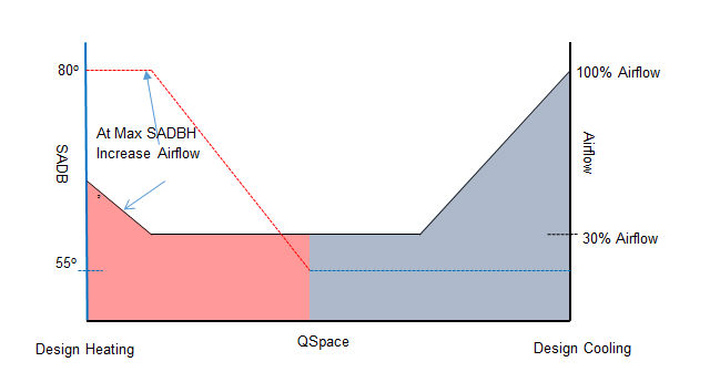
The minimum cooling airflow defaults to 30% and can be overridden by changing the VAV Minimum Cooling Airflow value on the terminal device tab of the system properties. In cooling mode, the supply air dry bulb is fixed while the supply airflow is varied to match the load. While the thermostat signal is in the deadband region (essentially, no load condition), the Single Zone VAV unit will continue to deliver minimum airflow at the SADBC setpoint. However, once the control thermostat senses that the room temperature has fallen below the heating thermostat setpoint, the cooling coil is deactivated and the heating coil becomes active. In heating mode, the supply airflow is maintained at its minimum setting and SADBH is varied to meet the space load. However, once the supply air dry bulb heating has reached its maximum (design) value, the airflow is increased to match the space load. The maximum heating-mode airflow is based on the VAV Minimum Heating Airflow value defined on the terminal device tab of the system properties. The control scheme over the range of space loads is shown in the diagram below.
Design Considerations
Since the Single Zone VAV air handler and coils are located at the zone level, the design cooling airflow is block at the zone level. This means that the total cooling design airflow across the system is the sum of the zone block airflows rather than the block airflow at the time of the system block. The system checksums will display the sum of the zone block airflows (collection of zone-level fans) rather than the system block airflow (which would only be correct if the fan were at the system level).
DesignClgSupplyAirflowzn = QBlockClgSpaceSensiblezn / [k * (DsRmdbc – SADBC)]
DesignClgSupplyAirflowsys = ∑DesignClgSupplyBlockAirflowzn
The zone design heating airflow will equal the sum of the design VAV heating airflows (the VAV maximum heating airflow setting as defined on the Create Room – Airflows screen). However, if the VAV maximum heating airflow value has not been defined, the VAV minimum cooling airflow is used instead. The maximum heating for a room occurs when the heating airflow and SADB are both at their maximums. If the AHU serves more than one room, the design heating supply airflow is the sum of the maximum heating supply airflows from the attached rooms:
DesignHtgSupplyAirflowzn = ∑MaxHtgSupplyAirflowrm
The system checksums represents the sum of the zone AHU’s and so will need to display the sum-of-the peak zone heating airflows (which also equals the sum-of-the-peak room heating design airflows).
DesignHtgSupplyAirflowsys = ∑ DesignHtgSupplyAirflowzn
The zone AHU’s design heating supply air dry bulb is based on the largest SADBH required after scanning all the rooms attached to a particular zone. First, the required SADBHrm is calculated for each room based on that room’s design supply heating airflow, design space sensible heating load, and DsRmdbhrm:
SADBHrm = DsRmdbhrm - QHtgSpaceSensRequiredrm / [k * DesignHtgSupplyAirflowrm]
Then the highest of these values is used to set the design value of SADBH for the zone-level AHU.
SADBHzn = Largest of [SADBHrm] for rooms attached to this zone
The design heating capacity is determined by first calculating the entering coil condition at the winter design condition:
Cedbhzn =[ (DesignHtgSupplyAirflowzn – DesignVentAirflowz) * Radbh + DesignVentAirflow*TVentDeckLvg] / DesignHtgSupplyAirflow
The zone-level AHU’s heating capacity is then given by:
QMainHtgCapacityzn = k * DesignHtgSupplyAirflowzn * (SADBHzn - Cedbhzn)
Because the SADBHzn is determined by finding the highest SADBHrm from all the rooms attached to that zone AHU, a net space sensible oversizing occurs for the rooms whose required SADBHrm was less than SADBHzn:
QHtgSpaceSensActualrm = k * DesignHtgSupplyAirflowrm * (SADBHzn – Cedbhrm)
QHtgSpaceSensOversizing = QHtgSpaceSensRequiredrm – QHtgSpaceSensActualrm
= k * DesignHtgSupplyAirflowrm * (SADBHrm – SADBHzn)
Zoning Considerations
Since the Single Zone VAV system does not have reheat coils at the room terminal units and because the thermostat sensor is typically located in just one of the rooms attached to the zone-level AHU, all rooms will receive the same temperature and supply airflow fraction as the “control” room. Therefore, it is extremely important to assign rooms with similar thermal loading to their parent zone-level AHU, i.e., the attached rooms facades (if any) should face the same direction and have nearly identical internal load schedules and load/floor area. Wild room temperature swings can occur if the control room’s thermal profile is not similar to the other attached rooms. Of course, if an AHU is assigned to each room, i.e., each room is its own zone, this consideration becomes moot.
Simulation notes
The program simulation is modeled in hour increments which can cause “non-reality” incidents. For example, the cooling coil would normally deactivate when the thermostat falls below the heating thermostat; however, if the introduction of minimum cooling airflow is the cause of the room temperature falling below the heating thermostat, the cooling coil will be off for part of the hour which is modeled by calculating an average SADBC for the hour instead of forcing DsnSADBC the entire hour.
Variable Refrigerant Flow
A typical Heat Recovery type Variable Refrigerant Flow (VRF) system consists of one outdoor unit and multiple indoor units. The compressor in this system is variable speed and controls the flow of refrigerant to the indoor units. A heat recovery VRF system has three modes of operation - Cooling only, Simultaneous heating and cooling and Heating only.
Indoor Unit
The indoor unit is essentially a DX fan coil. It consists of one DX coil and a three speed fan. Fan speeds are designated as H (100% airflow), L (70% airflow) and LL (10% airflow). The fan operates at minimum speed during the heating mode. Indoor units are typically unducted however. There are two models that can handle small duct systems (up to 300 Pa). The indoor unit is piped to a branch selector. This branch selector controls the flow of refrigerant to the fan coil unit. If the fan coil calls for cooling, the branch selector sends liquid refrigerant to the fan coil and the fan coil acts like an evaporator. If the fan coil calls for heating, then the branch selector sends hot gas to the fan coil and the fan coil acts like a condenser.
Since the branch selector controls the refrigerant flow and it always has access to both hot gas (for heating) and liquid refrigerant (for cooling) the fan coil is able to switch between heating and cooling mode very quickly. Indoor units can handle up to 10% outside air. Any additional ventilation requirements must be handled by an optional ventilation unit.
Each indoor unit has its own thermostat to control space conditions. Typical supply air temperatures for the indoor unit are 50°F in cooling and 100°F in heating. An optional electric or hot water coil can be added to the unit.
Airside simulation
When the room drift temperature rises above the cooling thermostat, the cooling coil is engaged at a constant cooling supply air temperature for the a percentage of the hour that it takes to bring the room temperature down to the cooling thermostat temperature. This heat is rejected to the refrigerant condenser loop. For the portion of the hour that the cooling coil is de-energized, the supply air will remain at the return/outside air dry bulb temperature (plus fan heat).
When the room drift temperature drops below the heating thermostat, the heating coil is engaged at a constant heating supply air temperature for the a percentage of the hour that it takes to bring the room temperature up to the heating thermostat temperature. The indoor unit will remove heat from the refrigerant condenser loop. For the portion of the hour that the cooling coil is de-energized, the supply air will remain at the return/outside air dry bulb temperature (plus fan heat).
Outdoor Unit
The outdoor unit consists of two condenser coils, two condenser fans, a variable speed compressor, and a reversing valve. The compressor operation is controlled by suction pressure. When operating in Cooling mode, the compressor speed varies to maintain a constant evaporator pressure. When operating in Heating mode, the compressor speed varies to maintain constant condensing pressure.
The operating mode of the condensing unit is controlled by the net load on the system. For example, if the net load on the system is cooling (cooling load + heating load = net cooling load) the unit operates in cooling mode and follows the primary unloading curve. Similarly, if the net load on the system is heating (cooling load + heating load = net heating load) the unit operates in heating mode and follows the secondary unloading curve. In all cases, the compressor capacity will modulate to exactly match the load on the system.
Variable Volume Reheat
VAV RH (30% Min Flow Default)
Variable Volume Reheat (30% Min Flow Default)
Note, there are two versions of this system:
● VAV RH (30% Min Flow Default) (DX): Variable Volume Reheat (30% Min Flow Default) (Direct Expansion)
● VAV RH (30% Min Flow Default) (CW): Variable Volume Reheat (30% Min Flow Default) (Chilled Water)
The only difference between these two systems is the Direct Expansion version uses a direct expansion cooling coil whereas the Chilled Water version uses a chilled water cooling coil.
The design is block cooling capacity and block air. This system is composed of a central VAV fan located on the cold deck that supplies conditioned air to each room's VAV box. The individual rooms may see a variable air quantity depending upon the cooling load and the minimum room airflow setting. A reheat coil in each VAV box is available to reheat the conditioned air if necessary at part load conditions. Return air is drawn from a common return air plenum where loads to return air are picked up from all rooms and brought back to the ROA deck for mixing with outside air.
System Simulation
For the case when no minimum stops exist, the following events will occur. When the drift temperature rises above this hour's cooling thermostat set point, the VAV box opens and delivers a proportionate quantity of supply air to the space, i.e., only enough cool supply air is added to bring down and maintain the room at this hour's cooling thermostat setpoint. When the drift temperature falls below this hour's heating thermostat setpoint, the VAV box is fully closed and neither heating nor cooling is possible by the main system since no supply airflow is available. As long as the room drift temperature is below the cooling thermostat setpoint this hour, the VAV box is fully closed. While the drift temperature is within the deadband region, there is no air movement and absolutely no mechanical heating or cooling can occur in the room by the main system.
For the case where minimum stops exist, the sequence of events is as follows. The VAV box is initially fixed at the reheat minimum airflow setting. Introduction of this cool air will drive the room temperature downward if the space cooling load is not great enough. The reheat coil will be energized only if the room temperature starts dropping below this hour's heating thermostat set point. If the admittance of this minimum quantity of conditioned air does not bring the room temperature below the cooling thermostat during times of high sensible load, the VAV box is opened past the minimum stop position until there is adequate cooling airflow to satisfy the cooling load.
Note that shutting off mechanical cooling does not shut off the VAV supply fan; if the fan schedule reads 1% or greater the supply fan will modulate accordingly, supplying untreated return/outside air to the terminal boxes that are open. However, if the supply fan is scheduled off for a particular hour, no mechanical cooling or mechanical heating is possible.
System Options
1. The value of minimum outside air nominally follows the outside air schedule. The amount of outside air introduced into the ROA deck may be greater than the ventilation minimum if an outside air economizer or nighttime purge is activated this hour.
In addition, the amount of outside air brought into a particular room is a function of how much cold deck air is needed by the room. If, for example, the drift temperature is below the cooling thermostat, the cold deck is closed and no outside air can be admitted (unless a reheat minimum has been specified). When the drift temperature is above the cooling thermostat, a proportional amount of outside air is admitted into the space.
If the main cooling fan is scheduled at zero percent for a particular hour, no ventilation airflow can be delivered to any of the rooms.
2. The cooling supply fan (entered as the main cooling fan) is available whenever the schedule reads 1% or greater. Its energy consumption will be proportional to the system cooling load for that hour. The supply fan may not be duty cycled during the cooling mode.
3. Specifying fan cycling on the availability manager tab of the system properties will allow the supply fan to cycle with the heating load for rooms which have minimum reheat airflow scheduled during unoccupied hours. Fan cycling can only apply to rooms that have a design reheat minimum airflow > 0 and their reheat minimum schedule reading > 0% for the hour(s) that the people schedule reads 5% or less.
4. Supply air temperature reset can be defined using the temperature control in the controls tab of the system properties.
5. Reheat Minimum. A reheat minimum will determine the minimum airflow into the space each hour. A reheat coil is assumed to be located at the terminus of each room's VAV box. A default value of 30% of the design room cooling airflow is assumed.
Application Notes
1. Warning: hours in which the reheat minimum is scheduled at 0%, no heating can take place.
2. While supply air reset control will save cooling energy, the room relative humidity will be higher and the VAV fan will consume more energy.
3. Humidity compensated controls can be implemented by using the humidity controller on the controls tab of the system properties to modify the default settings. By using the option supply air reset per maximum, for example, whenever a room relative humidity is greater than the design room relative humidity, the room's VAV dampers will continue to open until the room relative humidity is lowered to the design room relative humidity.
Alternatively, by specifying the option supply air reset per multizone maximum avg, whenever the return air relative humidity is greater than the design system relative humidity (which is the average of the design room relative humidities for the zones served by the system), supply air reset controls are deactivated and the main cooling coil leaving air temperature is depressed to its design value for that hour.
VAV w/ Baseboard Heating
The design is block tons and block air. This system is composed of a variable volume fan located on the cold deck that supplies conditioned air to each room's VAV box. The individual rooms see a variable air quantity proportional to the cooling load. Return air is drawn from a common return air plenum where loads to return air are picked up from all rooms and brought back to the ROA deck for mixing with outside air.
System Simulation
For the case when no minimum stops exist, the following events will occur. When the drift temperature rises above this hour's cooling thermostat set point, the VAV box opens and delivers a proportionate quantity of supply air to the space, i.e., only enough cool supply air is added to bring down and maintain the room at this hour's cooling thermostat setpoint. When the drift temperature falls below this hour's heating thermostat setpoint, the heating load is handled by a radiation heating unit that responds to the room thermostat, i.e., enough heat is added to the space to bring up and maintain the room at the heating thermostat set point. As long as the room drift temperature is below the cooling thermostat setpoint this hour, the VAV box is fully closed. While the drift temperature is within the dead band region, there is no air movement and absolutely no heating or cooling can take place within the room.
For the case where reheat minimums exist, the sequence of events is as follows. The VAV box is initially fixed at the reheat minimum airflow setting. Introduction of this cool air may drive the room temperature downward if the cooling load is low enough. The radiation heating unit will be energized only if the room temperature starts dropping below this hour's heating thermostat setpoint. If the admittance of this minimum quantity of conditioned air does not bring the room temperature below the cooling thermostat during times of high sensible load, the VAV box is opened past the minimum stop position until there is adequate cooling airflow to satisfy the load.
Note that shutting off mechanical cooling does not shut off the VAV supply fan; if the fan schedule reads 1% or greater the supply fan will modulate accordingly, supplying untreated return/outside air to the terminal boxes that are open. However, if the supply fan is scheduled off for a particular hour, no mechanical cooling is possible.
System Options
1. The value of minimum outside air nominally follows the outside air schedule. The amount of outside air introduced into the ROA deck may be greater than the ventilation minimum if an outside air economizer or nighttime purge is activated this hour.
In addition, the amount of outside air brought into a particular room is a function of how much cold deck air is needed by the room. If, for example, the drift temperature is below the cooling thermostat, the cold deck is closed and no outside air can be admitted (unless a reheat minimum has been specified). When the drift temperature is above the cooling thermostat, a proportional amount of outside air is admitted into the space.
If the main cooling fan is scheduled at zero percent for a particular hour, no ventilation airflow can be delivered to any of the rooms.
2. The cooling supply fan (entered as the main cooling fan) is available whenever the schedule reads 1% or greater. Its energy consumption will be proportional to the system cooling load for that hour. The supply fan may not be duty cycled during the cooling mode.
3. Specifying fan cycling on the availability manager tab of the system properties will allow the supply fan to cycle with the heating load for rooms which have minimum reheat airflow scheduled during unoccupied hours. Fan cycling can only apply to rooms that have a design reheat minimum airflow > 0 and their reheat minimum schedule reading > 0% for the hour(s) that the people schedule reads 5% or less.
4. Supply air temperature reset can be defined using the temperature control in the controls tab of the system properties.
5. Reheat Minimum. A reheat minimum will determine the minimum airflow into the space each hour. A reheat coil is assumed to be located at the terminus of each room's VAV box. A default value of 30% of the design room cooling airflow is assumed.
Application Notes
● While supply air reset control will save cooling energy, the room relative humidity will be higher and the VAV fan will consume more energy.
● The shutoff VAV system is almost identical to the Variable Air Volume Reheat (VRH) system except that VAV assumes radiation heating (with no reheat minimum) while VRH uses a reheat coil (with a 30% reheat minimum) for heating.
● Humidity compensated controls can be implemented by using the humidity controller on the controls tab of the system properties to modify the default settings. By using the option supply air reset per maximum, for example, whenever a room relative humidity is greater than the design room relative humidity, the room's VAV dampers will continue to open until the room relative humidity is lowered to the design room relative humidity.
Alternatively, by specifying the option supply air reset per multizone maximum avg, whenever the return air relative humidity is greater than the design system relative humidity (which is the average of the design room relative humidities for the zones served by the system), supply air reset controls are deactivated and the main cooling coil leaving air temperature is depressed to its design value for that hour.
Zone HVAC
VAV PTAC
The design is block air and block cooling capacity.
A separate cooling/heating heat pump is located in each zone. Each unit can draw return air either from a return air plenum above the particular room (return air assignments greater than zero) or recirculate air within the room (return air assignments are zero). The design cooling and heating supply air temperatures user input. The fans are variable volume.
System Simulation
When the room drift temperature rises above the room cooling thermostat, the cooling coil is energized (at a constant cooling supply air temperature) for a percentage of the hour that it takes to bring the room temperature down to the cooling thermostat temperature. This heat is rejected to the condenser loop. For the portion of the hour that the cooling coil is de-energized, the supply air will remain at the return/outside air dry bulb temperature (plus supply fan heat).
When the room drift point temperature drops below the room heating thermostat, the heating coil is energized (at a constant heating supply air temperature) for a percentage of the hour that it takes to bring the room temperature up to the heating thermostat temperature. The heat pump will remove heat from the condenser loop, thereby lowering its temperature. For the portion of the hour that the heating coil is de-energized, the supply air will remain at the return/outside air dry bulb temperature (plus supply fan heat).
When the room drift temperature lies within the deadband, the supply air will initially remain at the return/outside air dry bulb (plus fan heat).
System Options
1. The value of minimum ventilation airflow will be proportional to the percentage defined by the outside air schedule. The value of outside airflow may be greater than the nominal value if an economizer or nighttime purge is activated.
2. The value of outside airflow may be less than the nominal ventilation value if the supply fan (entered as the main cooling fan) has been scheduled at less than 100%; the outside air percentage for a particular hour will be multiplied by the main cooling fan utilization percent for that hour. If the supply fan has been scheduled off for a particular hour, no outside air can be delivered to the rooms.
3. The supply fan is available whenever the schedule reads 1% or greater. Its energy consumption will be proportional to the system cooling load for that hour. The minimum cooling airflow defaults to 30% and can be overridden by changing the VAV Minimum Cooling Airflow value on the Create Room – Airflows screen. In cooling mode, the supply air dry bulb is fixed while the supply airflow is varied to match the load. While the thermostat signal is in the deadband region (essentially, no load condition), the unit will continue to deliver minimum airflow at the SADBC setpoint. However, once the control thermostat senses that the room temperature has fallen below the heating thermostat setpoint, the cooling coil is deactivated and the heating coil becomes active. In heating mode, the supply airflow is maintained at its minimum setting and SADBH is varied to meet the space load. However, once the supply air dry bulb heating has reached its maximum (design) value, the airflow is increased to match the space load. The maximum heating mode airflow is based on the VAV Minimum Heating Airflow value defined on the Create Rooms – Airflows screen.
4. Neither the cooling or heating supply air temperature may be reset using supply air reset controls since the cooling supply air temperature is cycled at a constant temperature and the heating supply air temperature responds to the room thermostat.
Application Notes
● For PTHP systems, the unit can be oversized to include a safety factor by entering the cooling design capacity and heating design capacity (on the sizing tab of the system properties) as something larger than 100% of design cooling or heating capacity respectively.
● If the fans are to be cycled during unoccupied hours, enter the fan cycling information on the availability manager tab in the system properties.
VAV Unit Ventilator
A separate unit ventilator, including air handler and heating coil, is located in each room (on the hot deck at the room level). The design heating supply air temperature is assumed to be 95°F unless overridden by user input to the Airflow Design Temperatures screen.
System Simulation
The supply fan follows the main heating fan schedule in a time-clock fashion, bringing in outside air through the main heating coil according to the ventilation schedule.
When the room drift temperature rises above the room heating thermostat, the heating coil is de-activated, allowing the space temperature to drift upward. Since the supply air will be at the return/outside air dry bulb temperature (plus fan heat), scheduling outside air into the space will temper this effect to some degree.
When the room drift temperature drops below the room heating thermostat, the heating coil is modulated to produce a supply air dry bulb that will bring the room temperature up to the heating thermostat temperature.
System Options
1. The value of minimum ventilation airflow will be proportional to the percentage defined by the outside air schedule. The value of outside airflow may be greater than the nominal value if an economizer is activated.
The value of outside airflow may be less than the nominal ventilation value if the supply fan (entered as the main cooling fan) has been scheduled at less than 100%; the outside air percentage for a particular hour will be multiplied by the main heating fan utilization percent for that hour. If the supply fan has been scheduled off for a particular hour, no outside air can be delivered to the rooms.
2. The supply fan is available whenever the schedule reads 1% or greater. Its energy consumption will be proportional to the system cooling load for that hour. The minimum cooling airflow defaults to 30% and can be overridden by changing the VAV Minimum Cooling Airflow value on the Create Room – Airflows screen. In cooling mode, the supply air dry bulb is fixed while the supply airflow is varied to match the load. While the thermostat signal is in the deadband region (essentially, no load condition), the unit will continue to deliver minimum airflow at the SADBC setpoint. However, once the control thermostat senses that the room temperature has fallen below the heating thermostat setpoint, the cooling coil is deactivated and the heating coil becomes active. In heating mode, the supply airflow is maintained at its minimum setting and SADBH is varied to meet the space load. However, once the supply air dry bulb heating has reached its maximum (design) value, the airflow is increased to match the space load. The maximum heating mode airflow is based on the VAV Minimum Heating Airflow value defined on the Create Rooms – Airflows screen.
Application Notes
● If the fans are to be cycled during unoccupied hours, enter the fan cycling information on the availability manager tab in the system properties.
● Internal rooms (rooms with no walls, roofs, etc.) should be provided with adequate outside air if internal loads are scheduled; otherwise, the room temperature may go out of control.
● Since the ventilation air brought into the space will create "positive" building pressure, it is suggested that infiltration be scheduled opposite the outside air schedule, e.g., for outside air scheduled at 40% for a particular hour, the infiltration schedule should read (100-40) = 60%.
VAV Fan Coil
The design is block air and block cooling capacity.
A separate fan coil unit, including air handler and cooling and heating coils, is assumed for each zone. Central heating and cooling plants are assumed to handle the heating and cooling coil loads. Plenum return air loads are allowed although the assumption is that the return air is pulled from above the individual zones. If the fan coils are floor mounted units the lighting return air assignments should be set at zero. The design cooling and heating supply air temperatures are determined from either the Design Phase or user input and cannot be overridden by outside air reset schedules. The fans are variable volume.
System Simulation
When the zone drift temperature rises above the room cooling thermostat, the cooling coil is modulated to produce a supply air dry bulb that will bring the space down to the cooling thermostat temperature.
When the room drift temperature drops below the room heating thermostat, the heating coil is modulated to produce a supply air dry bulb that will bring the room temperature up to the heating thermostat temperature.
When the room drift temperature lies within the deadband, the supply air will be at the return/outside air dry bulb temperature (plus fan heat). If necessary, the return/outside air mixture will be heated or cooled to prevent the room temperature from going out of the deadband because of the introduction of significant quantities of cold or hot ventilation air.
System Options
1. The value of minimum ventilation airflow will be proportional to the percentage defined by the outside air schedule. The value of outside airflow may be greater than the nominal value if an economizer or nighttime purge is activated.
The value of outside airflow may be less than the nominal ventilation value if the supply fan (entered as the main cooling fan) has been scheduled at less than 100%; the outside air percentage for a particular hour will be multiplied by the main cooling fan utilization percent for that hour. If the supply fan has been scheduled off for a particular hour, no outside air can be delivered to the rooms.
2. The supply fan is available whenever the schedule reads 1% or greater. Its energy consumption will be proportional to the system cooling load for that hour. The minimum cooling airflow defaults to 30% and can be overridden by changing the VAV Minimum Cooling Airflow value on the Create Room – Airflows screen. In cooling mode, the supply air dry bulb is fixed while the supply airflow is varied to match the load. While the thermostat signal is in the deadband region (essentially, no load condition), the unit will continue to deliver minimum airflow at the SADBC setpoint. However, once the control thermostat senses that the room temperature has fallen below the heating thermostat setpoint, the cooling coil is deactivated and the heating coil becomes active. In heating mode, the supply airflow is maintained at its minimum setting and SADBH is varied to meet the space load. However, once the supply air dry bulb heating has reached its maximum (design) value, the airflow is increased to match the space load. The maximum heating mode airflow is based on the VAV Minimum Heating Airflow value defined on the Create Rooms – Airflows screen.
3. Since the fan coil heating and cooling supply air temperatures respond to the room thermostat, supply air reset control is not possible.
Application Notes
● The program assumes that the fan coil system is four-pipe (heating and cooling available all year round). To input a two-pipe fan coil system, the user should indicate which months the heating and cooling functions are to be locked out when creating the main cooling and heating schedules.
● If the fans are to be cycled during unoccupied hours, enter the fan cycling information on the availability manager tab in the system properties.
VAV PTHP
The design is block air and block cooling capacity.
A separate cooling/heating heat pump is located in each zone. Each unit can draw return air either from a return air plenum above the particular room (return air assignments greater than zero) or recirculate air within the room (return air assignments are zero). The design cooling and heating supply air temperatures are determined from either the Design Phase or user input and cannot be overridden by outside air reset schedules. The fans are variable volume.
System Simulation
When the room drift temperature rises above the room cooling thermostat, the cooling coil is energized (at a constant cooling supply air temperature) for a percentage of the hour that it takes to bring the room temperature down to the cooling thermostat temperature. This heat is rejected to the condenser loop. For the portion of the hour that the cooling coil is de-energized, the supply air will remain at the return/outside air dry bulb temperature (plus supply fan heat).
When the room drift point temperature drops below the room heating thermostat, the heating coil is energized (at a constant heating supply air temperature) for a percentage of the hour that it takes to bring the room temperature up to the heating thermostat temperature. The heat pump will remove heat from the condenser loop, thereby lowering its temperature. For the portion of the hour that the heating coil is de-energized, the supply air will remain at the return/outside air dry bulb temperature (plus supply fan heat).
When the room drift temperature lies within the deadband, the supply air will initially remain at the return/outside air dry bulb (plus fan heat).
System Options
1. The value of minimum ventilation airflow will be proportional to the percentage defined by the outside air schedule. The value of outside airflow may be greater than the nominal value if an economizer or nighttime purge is activated.
The value of outside airflow may be less than the nominal ventilation value if the supply fan (entered as the main cooling fan) has been scheduled at less than 100%; the outside air percentage for a particular hour will be multiplied by the main cooling fan utilization percent for that hour. If the supply fan has been scheduled off for a particular hour, no outside air can be delivered to the rooms.
2. The supply fan is available whenever the schedule reads 1% or greater. Its energy consumption will be proportional to the system cooling load for that hour. The minimum cooling airflow defaults to 30% and can be overridden by changing the VAV Minimum Cooling Airflow value on the Create Room – Airflows screen. In cooling mode, the supply air dry bulb is fixed while the supply airflow is varied to match the load. While the thermostat signal is in the deadband region (essentially, no load condition), the unit will continue to deliver minimum airflow at the SADBC setpoint. However, once the control thermostat senses that the room temperature has fallen below the heating thermostat setpoint, the cooling coil is deactivated and the heating coil becomes active. In heating mode, the supply airflow is maintained at its minimum setting and SADBH is varied to meet the space load. However, once the supply air dry bulb heating has reached its maximum (design) value, the airflow is increased to match the space load. The maximum heating mode airflow is based on the VAV Minimum Heating Airflow value defined on the Create Rooms – Airflows screen.
3. Neither the cooling or heating supply air temperature may be reset using supply air reset controls since the cooling supply air temperature is cycled at a constant temperature and the heating supply air temperature responds to the room thermostat.
Application Notes
● For PTHP systems, the unit can be oversized to include a safety factor by entering the cooling design capacity and heating design capacity (on the sizing tab of the system properties) as something larger than 100% of design cooling or heating capacity respectively.
● If the fans are to be cycled during unoccupied hours, enter the fan cycling information on the availability manager tab in the system properties.
VAV WSHP
The design is block air and block cooling capacity.
A separate WSHP unit is assumed for each room. Each unit can draw return air either from a return air plenum above the particular room or recirculate air within the room. The fans are variable volume.
In the heating mode, the evaporative coil acts as a condenser coil by drawing heat from the condenser loop. If not enough heat is available from the condenser loop, i.e., if the loop temperature has dropped below 60 F, a backup heat source (electric, gas, oil, etc.) is assumed to provide sufficient heat to the condenser loop. In the cooling mode, condenser heat is rejected to the loop. If the loop temperature exceeds 90 F, the heat is rejected to a closed loop cooling tower.
System Simulation
When the room drift temperature rises above the room cooling thermostat, the cooling coil is energized (at a constant cooling supply air temperature) for a percentage of the hour that it takes to bring the room temperature down to the cooling thermostat temperature. This heat is rejected to the condenser loop. For the portion of the hour that the cooling coil is de-energized, the supply air will remain at the return/outside air dry bulb temperature (plus supply fan heat).
When the room drift temperature drops below the room heating thermostat the heating coil is energized (at a constant heating supply air temperature) for a percentage of the hour that it takes to bring the room temperature up to the heating thermostat temperature. The heat pump will remove heat from the condenser loop, thereby lowering its temperature. For the portion of the hour that the heating coil is de-energized, the supply air will remain at the return/outside air dry bulb temperature (plus supply fan heat).
When the room drift temperature lies within the deadband, the supply air will initially remain at the return/outside air dry bulb temperature (plus supply fan heat).
System Options
1. The value of minimum ventilation airflow will be proportional to the percentage defined by the outside air schedule. The value of outside airflow may be greater than the nominal value if an economizer or nighttime purge is activated.
The value of outside airflow may be less than the nominal ventilation value if the supply fan has been scheduled at less than 100%; the outside air percentage for a particular hour will be multiplied by the main cooling fan utilization percent for that hour. If the supply fan has been scheduled off for a particular hour, no outside air can be delivered to the rooms.
2. The supply fan is available whenever the schedule reads 1% or greater. Its energy consumption will be proportional to the system cooling load for that hour. The minimum cooling airflow defaults to 30% and can be overridden by changing the VAV Minimum Cooling Airflow value on the Create Room – Airflows screen. In cooling mode, the supply air dry bulb is fixed while the supply airflow is varied to match the load. While the thermostat signal is in the deadband region (essentially, no load condition), the unit will continue to deliver minimum airflow at the SADBC setpoint. However, once the control thermostat senses that the room temperature has fallen below the heating thermostat setpoint, the cooling coil is deactivated and the heating coil becomes active. In heating mode, the supply airflow is maintained at its minimum setting and SADBH is varied to meet the space load. However, once the supply air dry bulb heating has reached its maximum (design) value, the airflow is increased to match the space load. The maximum heating mode airflow is based on the VAV Minimum Heating Airflow value defined on the Create Rooms – Airflows screen.
Application Notes
● Although the equipment configuration is different, the airside simulation of water source heat pump (WSHP) and packaged terminal air conditioners (PTAC) is similar.
● For WSHP systems, the unit can be oversized to include a safety factor by entering the cooling design capacity and heating design capacity (on the sizing tab of the system properties) as something larger than 100% of design cooling or heating capacity respectively.
● Humidity compensated controls can be implemented by using the humidity controller on the controls tab of the system properties to modify the default settings. By using the option supply air reset per maximum, for example, whenever a room relative humidity is greater than the design room relative humidity, the room's VAV dampers will continue to open until the room relative humidity is lowered to the design room relative humidity.
Alternatively, by specifying the option supply air reset per multizone maximum avg, whenever the return air relative humidity is greater than the design system relative humidity (which is the average of the design room relative humidities for the zones served by the system), supply air reset controls are deactivated and the main cooling coil leaving air temperature is depressed to its design value for that hour.
Radiant
VAV Heated Floor
The system is composed of high temperature radiant heating panels in the floor of the space and has no mechanical cooling capabilities.
System Simulation
When the room drift temperature falls below the hourly heating thermostat, the heat source is activated to maintain the room at the heating thermostat temperature. When the drift temperature rises above the room heating thermostat, the room temperature is allowed to drift upward.
System Options
1. Outside air is brought into the space via a separate outside air system. The value of minimum outside air airflow will be proportional to the percentage defined by the outside air schedule. Economizer controls are not available to the Heated Floor system; however, opening and shutting of windows can be simulated (even if there are no external walls) by specifying a dry bulb economizer type and scheduling the economizer available during occupied hours.
2. The only fan allowed to operate is the optional ventilation fan which will follow the outside air schedule in time clock fashion, i.e., if the schedule reads 80% for a particular hour, the fan will operate at full rpm for 80% of the hour and remain off the rest of the hour.
3. Reset Schedule. The radiation system responds only to the room heating thermostat and will thus ignore any OA reset schedule.
Application Notes
● If radiant panels are used as the heat source, the user should set back the heating thermostat several degrees from normal (for example, from 68 to 65 F) since radiant panels are able to maintain an equivalent comfort level at a lower room air temperature.
● Internal rooms (no walls, roofs, etc.) should be provided with adequate outside air to temper the room temperature if internal loads are scheduled; otherwise, the room temperature may go out of control.
● Since the ventilation air brought into the room will create "positive" building pressure, it is suggested that infiltration be scheduled opposite the outside air schedule, e.g., for outside air scheduled at 40% for a particular hour, the infiltration schedule should read (100 - 40) = 60%.
● A radiation system can support a plenum, but any loads assigned to return air will be conducted back out through the ceiling and any external plenum (wall and roof) surface areas.
VAV Chilled Ceiling
The system is composed of radiant panels in the ceiling of the space and has no mechanical heating capabilities.
System Simulation
When the room drift temperature rises above the hourly heating thermostat, the cooling panels are activated to maintain the room at the cooling thermostat temperature. When the drift temperature falls below the room cooling thermostat, the room temperature is allowed to drift upward.
System Options
1. Outside air is brought into the space via a separate outside air system. The value of minimum outside air airflow will be proportional to the percentage defined by the outside air schedule. Economizer controls are not available to the radiant cooling system; however, opening and shutting of windows can be simulated (even if there are no external walls) by specifying a dry bulb economizer type and scheduling the economizer available during occupied hours.
2. The only fan allowed to operate is the optional ventilation fan which will follow the outside air schedule in time clock fashion, i.e., if the schedule reads 80% for a particular hour, the fan will operate at full rpm for 80% of the hour and remain off the rest of the hour.
3. Reset Schedule. The radiation system responds only to the room cooling thermostat and will thus ignore any OA reset schedule.
Application Notes
● Internal rooms (no walls, roofs, etc.) should be provided with adequate outside air to temper the room temperature if internal loads are scheduled; otherwise, the room temperature may go out of control.
● Since the ventilation air brought into the room will create "positive" building pressure, it is suggested that infiltration be scheduled opposite the outside air schedule, e.g., for outside air scheduled at 40% for a particular hour, the infiltration schedule should read (100 - 40) = 60%.
● A radiation system can support a plenum, but any loads assigned to return air will be conducted back out through the ceiling and any external plenum (wall and roof) surface areas.
Constant Volume (CV)
Each system type contains description of the system and its components.
Zone HVAC
CV Fan Coil
The design is peak air and block cooling capacity.
A separate fan coil unit, including air handler and cooling and heating coils, is assumed for each zone. Central heating and cooling plants are assumed to handle the heating and cooling coil loads. Plenum return air loads are allowed although the assumption is that the return air is pulled from above the individual zones. If the fan coils are floor mounted units the lighting return air assignments should be set at zero. The design cooling and heating supply air temperatures are determined from either the Design Phase or user input and cannot be overridden by outside air reset schedules. The fans are constant volume while the coils are modulated to meet the load.
System Simulation
When the zone drift temperature rises above the room cooling thermostat, the cooling coil is modulated to produce a supply air dry bulb that will bring the space down to the cooling thermostat temperature.
When the room drift temperature drops below the room heating thermostat, the heating coil is modulated to produce a supply air dry bulb that will bring the room temperature up to the heating thermostat temperature.
When the room drift temperature lies within the deadband, the supply air will be at the return/outside air dry bulb temperature (plus fan heat). If necessary, the return/outside air mixture will be heated or cooled to prevent the room temperature from going out of the deadband because of the introduction of significant quantities of cold or hot ventilation air.
System Options
1. The value of minimum ventilation airflow will be proportional to the percentage defined by the outside air schedule. The value of outside airflow may be greater than the nominal value if an economizer or nighttime purge is activated.
2. The value of outside airflow may be less than the nominal ventilation value if the supply fan (entered as the main cooling fan) has been scheduled at less than 100%; the outside air percentage for a particular hour will be multiplied by the main cooling fan utilization percent for that hour. If the supply fan has been scheduled off for a particular hour, no outside air can be delivered to the rooms.
3. The supply fan is controlled in time clock fashion, i.e., if the schedule reads 80% for a particular hour, the fan will operate at full rpm for 80% of the hour and remain off the rest of the hour. Since the supply fan delivers conditioned air to the room, reducing the percent it can operate during a given hour will cause the cooling coil to modulate at a lower temperature (than normal) during the percent of the hour the fan is available. If the fan is not allowed to operate long enough, the room temperature will be allowed to drift, the amount dependent on the magnitude of the unmet space load.
4. Since the fan coil heating and cooling supply air temperatures respond to the room thermostat, supply air reset control is not possible.
Application Notes
● The program assumes that the fan coil system is four-pipe (heating and cooling available all year round). To input a two-pipe fan coil system, the user should indicate which months the heating and cooling functions are to be locked out when creating the main cooling and heating schedules.
● If the fans are to be cycled during unoccupied hours, enter the fan cycling information on the availability manager tab in the system properties.
CV PTHP
The design is peak air and peak cooling capacity.
A separate cooling/heating heat pump is located in each zone. Each unit can draw return air either from a return air plenum above the particular room (return air assignments greater than zero) or recirculate air within the room (return air assignments are zero). The design cooling and heating supply air temperatures are determined from either the Design Phase or user input and cannot be overridden by outside air reset schedules. The fans are constant volume while cooling coils are cycled to meet the load.
System Simulation
When the room drift temperature rises above the room cooling thermostat, the cooling coil is energized (at a constant cooling supply air temperature) for a percentage of the hour that it takes to bring the room temperature down to the cooling thermostat temperature. This heat is rejected to the condenser loop. For the portion of the hour that the cooling coil is de-energized, the supply air will remain at the return/outside air dry bulb temperature (plus supply fan heat).
When the room drift point temperature drops below the room heating thermostat, the heating coil is energized (at a constant heating supply air temperature) for a percentage of the hour that it takes to bring the room temperature up to the heating thermostat temperature. The heat pump will remove heat from the condenser loop, thereby lowering its temperature. For the portion of the hour that the heating coil is de-energized, the supply air will remain at the return/outside air dry bulb temperature (plus supply fan heat).
When the room drift temperature lies within the deadband, the supply air will initially remain at the return/outside air dry bulb (plus fan heat).
System Options
1. The value of minimum ventilation airflow will be proportional to the percentage defined by the outside air schedule. The value of outside airflow may be greater than the nominal value if an economizer or nighttime purge is activated.
The value of outside airflow may be less than the nominal ventilation value if the supply fan (entered as the main cooling fan) has been scheduled at less than 100%; the outside air percentage for a particular hour will be multiplied by the main cooling fan utilization percent for that hour. If the supply fan has been scheduled off for a particular hour, no outside air can be delivered to the rooms.
2. The supply fan is controlled in time clock fashion, i.e., if the schedule reads 80% for a particular hour, the fan will operate at full rpm for 80% of the hour and remain off the rest of the hour. Since the supply fan delivers conditioned air to the space, reducing the percent it can operate during a given hour will cause the cooling coil to cycle on more often during the percent of the hour the fan is available. If the fan is not allowed to operate long enough, the room temperature will be allowed to drift, the amount dependent on the magnitude of the unmet space load.
3. Neither the cooling or heating supply air temperature may be reset using supply air reset controls since the cooling supply air temperature is cycled at a constant temperature and the heating supply air temperature responds to the room thermostat.
Application Notes
● For PTHP systems, the unit can be oversized to include a safety factor by entering the cooling design capacity and heating design capacity (on the sizing tab of the system properties) as something larger than 100% of design cooling or heating capacity respectively.
● If the fans are to be cycled during unoccupied hours, enter the fan cycling information on the availability manager tab in the system properties.
CV PTAC
The design is peak air and peak cooling capacity.
A separate PTAC unit (located on the ROA deck) is assumed for each room. Each unit can draw return air either from a return air plenum above the particular room (return air assignments greater than zero) or recirculate air within the room (return air assignments are zero). The design cooling and heating supply air temperatures are user input. The fans are constant volume while the cooling coils are cycled to meet the load. Heating is assumed to be provided by electric resistance heat or by modulating hot water coils.
System Simulation
When the room drift temperature rises above the room cooling thermostat, the cooling coil is energized (at a constant cooling supply air temperature) for a percentage of the hour that it takes to bring the room temperature down to the cooling thermostat temperature. For the portion of the hour that the cooling coil is de-energized, the supply air will remain at the return/outside air dry bulb temperature (plus supply fan heat).
When the room drift temperature drops below the room heating thermostat the heating coil is energized (at a constant heating supply air temperature) for a percentage of the hour that it takes to bring the room temperature up to the heating thermostat temperature. For the portion of the hour that the heating coil is de-energized, the supply air will remain at the return/outside air dry bulb temperature (plus supply fan heat).
When the room drift temperature lies within the deadband, the supply air will initially remain at the return/outside air dry bulb temperature (plus supply fan heat). If necessary, the return/outside air mixture will be heated or cooled to prevent the room temperature from going out of the deadband because of the introduction of significant quantities of cold or hot ventilation air.
System Options
1. The value of minimum ventilation airflow will be proportional to the percentage defined by the outside air schedule. The value of outside airflow may be greater than the nominal value if an economizer or nighttime purge is activated.
The value of outside airflow may be less than the nominal ventilation value if the supply fan (entered as the main cooling fan) has been scheduled at less than 100%; the outside air percentage for a particular hour will be multiplied by the main cooling fan utilization percent for that hour. If the supply fan has been scheduled off for a particular hour, no outside air can be delivered to the rooms.
2. The supply fan is controlled in time clock fashion, i.e., if the schedule reads 80% for a particular hour, the fan will operate at full rpm for 80% of the hour and remain off the rest of the hour. Since the supply fan delivers conditioned air to the space, reducing the percent it can operate during a given hour will cause the cooling coil to cycle on more often during the percent of the hour the fan is available. If the fan is not allowed to operate long enough, the room temperature will be allowed to drift, the amount dependent on the magnitude of the unmet space load.
3. Neither the cooling or heating supply air temperature may be reset using supply air reset controls since the cooling supply air temperature is cycled at a constant temperature and the heating supply air temperature responds to the room thermostat.
Application Notes
● For PTAC systems, the unit can be oversized to include a safety factor by entering the cooling design capacity and heating design capacity (on the sizing tab of the system properties) as something larger than 100% of design cooling or heating capacity respectively.
● If the fans are to be cycled during unoccupied hours, enter the fan cycling information on the availability manager tab in the system properties.
CV Unit Ventilator
A separate unit ventilator, including air handler and heating coil, is located in each room (on the hot deck at the room level). The design heating supply air temperature is assumed to be 95°F unless overridden by user input to the Airflow Design Temperatures screen.
System Simulation
The supply fan follows the main heating fan schedule in a time-clock fashion, bringing in outside air through the main heating coil according to the ventilation schedule.
When the room drift temperature rises above the room heating thermostat, the heating coil is de-activated, allowing the space temperature to drift upward. Since the supply air will be at the return/outside air dry bulb temperature (plus fan heat), scheduling outside air into the space will temper this effect to some degree.
When the room drift temperature drops below the room heating thermostat, the heating coil is modulated to produce a supply air dry bulb that will bring the room temperature up to the heating thermostat temperature.
System Options
1. The value of minimum ventilation airflow will be proportional to the percentage defined by the outside air schedule. The value of outside airflow may be greater than the nominal value if an economizer is activated.
The value of outside airflow may be less than the nominal ventilation value if the supply fan (entered as the main cooling fan) has been scheduled at less than 100%; the outside air percentage for a particular hour will be multiplied by the main heating fan utilization percent for that hour. If the supply fan has been scheduled off for a particular hour, no outside air can be delivered to the rooms.
2. Supply Fan Controls. The supply fan (entered as the main cooling fan) is controlled in time clock fashion, i.e., if the schedule reads 80% for a particular hour, the fan will operate at full rpm for 80% of the hour and remain off the rest of the hour. Since the supply fan delivers conditioned air to the space, reducing the percent it can operate during a given hour will cause the heating coil to modulate at a higher supply air temperature during the percent of the hour the fan is available. If the fan is not allowed to operate long enough, the room temperature will be allowed to drift, the amount dependent on the magnitude of the unmet space load.
Application Notes
● If the fans are to be cycled during unoccupied hours, enter the fan cycling information on the availability manager tab in the system properties.
● Internal rooms (rooms with no walls, roofs, etc.) should be provided with adequate outside air if internal loads are scheduled; otherwise, the room temperature may go out of control.
● Since the ventilation air brought into the space will create "positive" building pressure, it is suggested that infiltration be scheduled opposite the outside air schedule, e.g., for outside air scheduled at 40% for a particular hour, the infiltration schedule should read (100-40) = 60%.
CV WSHP
The design is peak air and peak cooling capacity.
A separate WSHP unit is assumed for each room. Each unit can draw return air either from a return air plenum above the particular room or recirculate air within the room. The fans are constant volume while the cooling coils are cycled to meet the cooling load.
In the heating mode, the evaporative coil acts as a condenser coil by drawing heat from the condenser loop. If not enough heat is available from the condenser loop, i.e., if the loop temperature has dropped below 60 F, a backup heat source (electric, gas, oil, etc.) is assumed to provide sufficient heat to the condenser loop. In the cooling mode, condenser heat is rejected to the loop. If the loop temperature exceeds 90 F, the heat is rejected to a closed loop cooling tower.
System Simulation
When the room drift temperature rises above the room cooling thermostat, the cooling coil is energized (at a constant cooling supply air temperature) for a percentage of the hour that it takes to bring the room temperature down to the cooling thermostat temperature. This heat is rejected to the condenser loop. For the portion of the hour that the cooling coil is de-energized, the supply air will remain at the return/outside air dry bulb temperature (plus supply fan heat).
When the room drift temperature drops below the room heating thermostat the heating coil is energized (at a constant heating supply air temperature) for a percentage of the hour that it takes to bring the room temperature up to the heating thermostat temperature. The heat pump will remove heat from the condenser loop, thereby lowering its temperature. For the portion of the hour that the heating coil is de-energized, the supply air will remain at the return/outside air dry bulb temperature (plus supply fan heat).
When the room drift temperature lies within the deadband, the supply air will initially remain at the return/outside air dry bulb temperature (plus supply fan heat).
System Options
1. The value of minimum ventilation airflow will be proportional to the percentage defined by the outside air schedule. The value of outside airflow may be greater than the nominal value if an economizer or nighttime purge is activated.
The value of outside airflow may be less than the nominal ventilation value if the supply fan has been scheduled at less than 100%; the outside air percentage for a particular hour will be multiplied by the main cooling fan utilization percent for that hour. If the supply fan has been scheduled off for a particular hour, no outside air can be delivered to the rooms.
2. Supply Fan Controls. The supply fan is controlled in time clock fashion, i.e., if the schedule reads 80% for a particular hour, the fan will operate at full rpm for 80% of the hour and remain off the rest of the hour. Since the supply fan delivers conditioned air to the space, reducing the percent it can operate during a given hour will cause the cooling coil to cycle on more often during the percent of the hour the fan is available. If the fan is not allowed to operate long enough, the room temperature will be allowed to drift, the amount dependent on the magnitude of the unmet space load.
Application Notes
● Although the equipment configuration is different, the airside simulation of water source heat pump (WSHP) and packaged terminal air conditioners (PTAC) is similar.
● For WSHP systems, the unit can be oversized to include a safety factor by entering the cooling design capacity and heating design capacity (on the sizing tab of the system properties) as something larger than 100% of design cooling or heating capacity respectively.
● Humidity compensated controls can be implemented by using the humidity controller on the controls tab of the system properties to modify the default settings. By using the option supply air reset per maximum, for example, whenever a room relative humidity is greater than the design room relative humidity, the room's VAV dampers will continue to open until the room relative humidity is lowered to the design room relative humidity.
Alternatively, by specifying the option supply air reset per multizone maximum avg, whenever the return air relative humidity is greater than the design system relative humidity (which is the average of the design room relative humidities for the zones served by the system), supply air reset controls are deactivated and the main cooling coil leaving air temperature is depressed to its design value for that hour.
Single Zone CV
The design is peak air and peak cooling capacity.
A separate single zone unit, including air handler and cooling and heating coils, is assumed for each zone. Each unit is located on the ROA deck and draws return air from a common return air plenum, i.e., the return air of the interior and perimeter rooms associated with a series of single zone units is uniformly mixed in the common return air plenum. The design cooling and heating supply air temperatures are determined from either the Design Phase or user input and cannot be overridden by outside air reset schedules. The fans are constant volume while the coils are cycled to meet the load.
Each zone assigned to this system will be given its own set of coils. For example, if 10 zones are assigned to an individual Single Zone CV system, 10 systems will be created, one per zone.
System Simulation
When the room drift temperature rises above the room cooling thermostat, the cooling coil is energized (at a constant cooling supply air temperature) for a percentage of the hour that it takes to bring the room temperature down to the cooling thermostat temperature. For the portion of the hour that the cooling coil is de-energized, the supply air will remain at the return/outside air dry bulb temperature (plus supply fan heat).
When the room drift temperature drops below the room heating thermostat the heating coil is energized (at a constant heating supply air temperature) for a percentage of the hour that it takes to bring the room temperature up to the heating thermostat temperature. For the portion of the hour that the heating coil is de-energized, the supply air will remain at the return/outside air dry bulb temperature (plus supply fan heat).
When the room drift temperature lies within the deadband, the supply air will initially remain at the return/outside air dry bulb temperature (plus supply fan heat). If necessary, the return/outside air mixture will be heated or cooled to prevent the room temperature from going out of the deadband because of the introduction of significant quantities of cold or hot ventilation air.
System Options
1. The value of minimum ventilation airflow will be proportional to the percentage defined by the outside air schedule. The value of outside airflow may be greater than the nominal value if an economizer or nighttime purge is activated.
The value of outside airflow may be less than the nominal ventilation value if the supply fan (entered as the main cooling fan) has been scheduled at less than 100%; the outside air percentage for a particular hour will be multiplied by the main cooling fan utilization percent for that hour. If the supply fan has been scheduled off for a particular hour, no outside air can be delivered to the rooms.
2. The supply fan is controlled in time clock fashion, i.e., if the schedule reads 80% for a particular hour, the fan will operate at full rpm for 80% of the hour and remain off the rest of the hour. Since the supply fan delivers conditioned air to the space, reducing the percent it can operate during a given hour will cause the cooling coil to cycle on more often during the percent of the hour the fan is available. If the fan is not allowed to operate long enough, the room temperature will be allowed to drift, the amount dependent on the magnitude of the unmet space load.
3. Neither the cooling or heating supply air temperature may be reset using supply air reset controls since the cooling supply air temperature is cycled at a constant temperature and the heating supply air temperature responds to the room thermostat.
Application Note
● Humidity compensated controls can be implemented by using the humidity controller on the controls tab of the system properties to modify the default settings. By using the option supply air reset per maximum, for example, whenever a room relative humidity is greater than the design room relative humidity, the room's VAV dampers will continue to open until the room relative humidity is lowered to the design room relative humidity.
● Alternatively, by specifying the option supply air reset per multizone maximum avg, whenever the return air relative humidity is greater than the design system relative humidity (which is the average of the design room relative humidities for the zones served by the system), supply air reset controls are deactivated and the main cooling coil leaving air temperature is depressed to its design value for that hour.
Terminal Reheat
The design is peak air and peak cooling capacity.
This system is composed of a central, constant volume fan located on the cold deck which delivers conditioned air at a constant cooling supply air temperature to each room's terminal unit. A reheat coil is located in each room's terminal unit to reheat the supply air when necessary. The return air is drawn from a common return air plenum; the perimeter and the interior rooms return air is assumed to be uniformly mixed before being seen by the central cooling coil.
System Simulation
A constant volume of air is delivered at a constant cooling supply air temperature to each room regardless of what the room temperatures are this hour. The admittance of this constant stream of cold air will depress the room temperature downward in the rooms not at their design cooling condition.
If the drift temperature falls below the heating thermostat in a particular room, the room reheat coil is activated to maintain the room temperature at the heating thermostat setpoint for that hour. Since the cooling coil is not controlled by the cooling thermostat (unless a supply air reset control is specified), it is advisable to lock cooling out rather than setting the cooling thermostat up during periods of non-operation.
System Options
1. The value of minimum ventilation airflow will be proportional to the percentage defined by the outside air schedule. The value of outside airflow may be greater than the nominal value if an economizer or nighttime purge is activated.
The value of outside airflow may be less than the nominal ventilation value if the supply fan has been scheduled at less than 100%; the outside air percentage for a particular hour will be multiplied by the main cooling fan utilization percent for that hour. If the supply fan has been scheduled off for a particular hour, no outside air can be delivered to the rooms.
2. The supply fan is controlled in time clock fashion, i.e., if the schedule reads 80% for a particular hour, the fan will operate at full rpm for 80% of the hour and remain off the rest of the hour. Since the supply fan delivers conditioned air to the space, reducing the percent it can operate during a given hour will cause the system to possibly lose control of the room temperature and humidity. If the fan is not allowed to operate long enough, the room temperature will be allowed to drift, the amount dependent on the magnitude of the unmet space load.
3. Specifying a supply air reset control will cause the cooling supply air temperature to be reset upward based on the worst case cooling room. This, in turn, will cause the room relative humidity to drift. The heating supply air temperature cannot be reset since the reheat coil must respond to the room thermostat. The preheat coil will, however, shift it's control point upward proportional to the amount that the cooling supply air temperature is reset upward.
4. Reset Schedules. Only the cold deck may be reset by outside air reset schedules. Unless a reset schedule is input by the user, the program will assume a constant cooling supply air dry bulb for all outside air conditions.
Application Note
● This system, when used without a supply air reset control, will provide the best humidity control at part load when compared to all other standard system types. The trade-off is that it will also consume the most energy.
Radiant
CV Heated Floor
CV Chilled Ceiling
Double Duct
Double Duct VAV
The design is block air and block cooling capacity.
System Description
This system is composed of a separate hot and cold deck that supplies air to each room's variable air volume mixing box. The single, variable air volume supply fan is located on the ROA deck and will modulate in proportion to the sum of the room hot and cold deck airflows. Return air is drawn from a common return air plenum; the return air from the associated interior and perimeter rooms is assumed to be uniformly mixed before being routed to the ROA deck.
Nonmixing Event
For nonmixing situations, the sequence of events is as follows. When the room drift temperature has risen above the room cooling thermostat the cold deck side of the room mixing box is opened. The resulting room airflow is proportional to the room's design cooling load. When the room drift temperature drops below the room heating thermostat, the hot deck side of the room mixing box opens. The resulting room heating airflow is assumed to be proportional to the room's design heating load. When the room drift temperature lies within the dead band region both the hot and the cold sides of the room mixing box are closed and no supply air is admitted to the space. It is possible for some rooms to be in the heating mode (using hot deck air only) and some rooms in the cooling mode (using cold deck air only) simultaneously since the hot and cold decks are separate.
Mixing Event
Mixing situations can occur in a room mixing box only when a reheat minimum airflow has been specified. A minimum stop defines the minimum amount of cold and hot deck airflow that must be delivered to each space. When the drift temperature rises above the room cooling thermostat, mixing can occur when the cooling airflow required to meet this hour's cooling load is less than the minimum stop airflow; the proportions of cold and hot deck airflow are then adjusted to control the room temperature to the cooling thermostat temperature. Similarly, when the drift temperature drops below the room heating thermostat, mixing can occur when the heating airflow required to meet this hour's heating load is less than the minimum stop; the proportions of cold and hot deck airflow are then adjusted to control the room temperature to the heating thermostat temperature. When the drift temperature lies within the dead band, the proportions of hot and cold deck airflow are adjusted to control the space at the beginning hour's room temperature.
Note that shutting off the cooling coil availability does not shut off the central air handler. The supply fan will modulate accordingly, supplying untreated return/outside air to the room mixing boxes that are open in response to the thermostat settings. However, if the supply fan is scheduled off for a particular hour, no mechanical cooling or heating is possible.
System Options
1. The value of minimum outside air nominally follows the outside air schedule. The amount of outside air introduced into the ROA deck may be greater than the ventilation minimum if an outside air economizer or nighttime purge is activated this hour.
In addition, the amount of outside air brought into a particular room is a function of how much supply air is needed by the room. If, for example, the drift temperature is in the dead band both the cold and hot decks are closed and no outside air can be admitted (unless a reheat minimum has been specified). When the drift temperature is above the cooling thermostat or below the heating thermostat, a proportional amount of outside air is admitted into the space.
If the supply fan has been scheduled off for a particular hour, no outside air can be delivered to the rooms.
2. The supply fan is available whenever the schedule reads 1% or greater for a particular hour. Its energy consumption will be proportional to the amount of supply airflow required each hour.
3. Input fan cycling on the availability manager tab of the systems properties will allow the supply fan to cycle with the heating load for rooms which have minimum reheat airflow scheduled during unoccupied hours. Fan cycling can only apply to rooms that have a design reheat minimum airflow > 0 and their reheat minimum schedule reading > 0% for the hour(s) that the people schedule reads 5% or less.
4. Supply air temperature reset control can be used to reset the cold deck temperature upward based on the worst case cooling room and reset the hot deck temperature downward based on the worst case heating room.
5. Reheat Minimum. A reheat minimum will determine the minimum airflow into the space each hour.
Application Notes
● The return/outside air mixture, which is the air routed through the ROA deck, is used on both decks. Consequently, when an economizer is specified, greatly increased heating loads can result since the ROA deck temperature will be controlled to the required cooling supply air temperature regardless of the cooling load. (Only one room out of ten may need cooling, for example.) Input of a supply air reset control will minimize the excess heating during unoccupied hours but will have minimal effects during occupied hours.
● Humidity compensated controls can be implemented by using the humidity controller on the controls tab of the system properties to modify the default settings. By using the option supply air reset per maximum, for example, whenever a room relative humidity is greater than the design room relative humidity, the room's VAV dampers will continue to open until the room relative humidity is lowered to the design room relative humidity.
Alternatively, by specifying the option supply air reset per multizone maximum avg, whenever the return air relative humidity is greater than the design system relative humidity (which is the average of the design room relative humidities for the zones served by the system), supply air reset controls are deactivated and the main cooling coil leaving air temperature is depressed to its design value for that hour.
Two-Fan Double Duct VAV
The design is block air and block cooling capacity.
System Description
This system is composed of a separate cold deck and a separate heating runaround deck that supply air to each room's mixing box. The cooling and heating supply fans are both variable air volume and will modulate in proportion to the sum of their respective room cooling and heating airflows.
Nonmixing Event
For nonmixing situations, the sequence of events is as follows. When the room drift temperature has risen above the room cooling thermostat the cold deck side of the room mixing box is opened. The resulting room airflow is proportional to the room's design cooling load. When the room drift temperature drops below the room heating thermostat, the runaround deck side of the room mixing box opens. The resulting room heating airflow is assumed to be proportional to the room's design heating load. When the room drift temperature lies within the deadband region both the supply and the runaround sides of the room mixing box are closed and no conditioned air is admitted to the space.
Mixing Event
Mixing situations can occur in a room mixing box only when a reheat minimum airflow has been specified. A minimum stop defines the minimum amount of cold deck airflow that must be delivered to each space. As long as the room drift temperature stays above the room heating thermostat no mixing takes place and the mixing box supplies air only from the cold deck. If, however, the room drift temperature falls below the heating thermostat settings, the hot deck also opens such that the mixture of the hot and cold deck airflow controls the room temperature to the heating thermostat. Thus, as long as the room drift temperature remains in the dead band region, the cold deck air quantity is equal to the room reheat minimum airflow.
Note that shutting off mechanical cooling does not shut off the cooling supply fan. If the cooling fan schedule reads 1% or greater the cold deck fan will modulate accordingly, supplying untreated return/outside air to the room mixing boxes that are open. However, if the main cooling fan has been scheduled off for a particular hour, no mechanical cooling is possible.
Similarly, shutting off the main heating coil does not shut off the heating supply fan. If the main heating fan schedule reads 1% or greater the heating supply fan will modulate accordingly, supplying untreated runaround air to the room mixing boxes that are open. However, if the main heating fan has been scheduled off for a particular hour, no mechanical heating is possible.
System Options
1. The value of minimum outside air nominally follows the outside air schedule. The amount of outside air introduced into the cold deck may be greater than the ventilation minimum if an outside air economizer or nighttime purge is activated this hour.
In addition, the amount of outside air brought into a particular room is a function of how much cold deck air is needed by the room. If, for example, the drift temperature is below the cooling thermostat, the cold deck is closed and no outside air can be admitted (unless a reheat minimum has been specified). When the drift temperature is above the cooling thermostat, a proportional amount of outside air is admitted into the space.
Note that scheduling the cooling supply fan off means that no outside air can be delivered to the rooms.
2. The cooling supply fan is available whenever the main cooling fan schedule reads 1% or greater for a particular hour. Its energy consumption will be proportional to the amount of cold deck airflow required each hour.
The heating supply fan is available whenever the main heating fan schedule reads 1% or greater for a particular hour. Its energy consumption will be proportional to the amount of runaround (heating) airflow required each hour.
3. Supply air reset control can be used to reset the cooling supply air temperature upward based on the worst case cooling room. The heating supply air temperature will be reset downward based on the worst case heating room.
4. Reheat Minimum. A reheat minimum will determine the minimum cold deck airflow into the space each hour.
Application Notes
● While supply air reset control will save cooling energy, the room relative humidity will be higher and the supply fans will consume more energy.
● Humidity compensated controls can be implemented by using the humidity controller on the controls tab of the system properties to modify the default settings. By using the option supply air reset per maximum, for example, whenever a room relative humidity is greater than the design room relative humidity, the room's VAV dampers will continue to open until the room relative humidity is lowered to the design room relative humidity.
Alternatively, by specifying the option supply air reset per multizone maximum avg, whenever the return air relative humidity is greater than the design system relative humidity (which is the average of the design room relative humidities for the zones served by the system), supply air reset controls are deactivated and the main cooling coil leaving air temperature is depressed to its design value for that hour.
Double Duct CV
System Description
The design is peak air and block cooling capacity.
This system is composed of a central, constant volume fan which delivers air via a hot and cold deck to the individual room mixing boxes. Return air is drawn from a common return air plenum; the return air from the associated interior and perimeter rooms is assumed to be uniformly mixed before being routed to the ROA deck.
System Simulation
A constant volume of air is delivered to each room as long as the supply fan is scheduled on. Once the drift temperature for the hour is known for all rooms, the program calculates the supply air temperature needed for each room.
If the room drift temperature rises above this hour’s cooling thermostat, the room supply air temperature will be controlled (by mixing hot and cold deck air) such that the room temperature is brought down and maintained at the room cooling thermostat.
If the room drift temperature falls below this hour’s heating thermostat, the room supply air temperature will be controlled (by mixing hot and cold deck air) such that the room temperature is brought up and maintained at the room heating thermostat.
If the drift temperature is within the deadband region, the room supply air temperature will be controlled such that the room temperature stays at the beginning drift temperature for this hour.
System Options
1. The value of minimum ventilation airflow will be proportional to the percentage defined by the outside air schedule. The value of the outside airflow may be greater than the nominal value if an economizer or nighttime purge is activated. The value of outside airflow may be less than the nominal ventilation value if the supply fan (entered as the main cooling fan) has been scheduled at less than 100%; the outside air percentage for a particular hour will be multiplied by the main cooling fan utilization percent for that hour. If the supply fan has been scheduled off for a particular hour, no outside air can be delivered to the rooms.
2. The supply fan is controlled in time clock fashion, i.e., if the schedule reads 80% for a particular hour, the fan will operate at full rpm for 80% of the hour and remain off the rest of the hour. Since the supply fan delivers conditioned air to the space, reducing the percent it can operate during a given hour will cause the cold deck to deliver a greater proportion of the supply air during the cooling mode or the hot deck to deliver a greater proportion of the supply air during the heating mode. If the fan is not allowed to operate long enough, the room temperature will be allowed to drift, the amount dependent on the magnitude of the unmet space load.
3. Specifying a supply air reset control will cause the program to reset the cooling supply air dry bulb upward based on the worst case cooling room and reset the heating supply air dry bulb downward based on the worst case heating room.
Application Notes
● The return/outside air moisture, i.e., the air routed through the ROA deck, is used by both the cold and hot decks. Consequently, when an economizer is specified, greatly increased heating loads can result since the ROA deck air will be controlled to the cooling supply air temperature dictated by the outside air reset schedule even if only one room in the system needs cooling. Specifying a supply air reset control will minimize the excess heating during unoccupied hours but will have minimal effects during occupied hours.
● Despite the differences in duct configuration, the airside energy requirements of double duct are identical to those of the multizone system if the system inputs are also identical.
● Humidity compensated controls can be implemented by using the humidity controller on the controls tab of the system properties to modify the default settings. By using the option supply air reset per maximum, for example, whenever a room relative humidity is greater than the design room relative humidity, the room's VAV dampers will continue to open until the room relative humidity is lowered to the design room relative humidity.
Alternatively, by specifying the option supply air reset per multizone maximum avg, whenever the return air relative humidity is greater than the design system relative humidity (which is the average of the design room relative humidities for the zones served by the system), supply air reset controls are deactivated and the main cooling coil leaving air temperature is depressed to its design value for that hour.
Chilled Beam and Induction
Each system type contains description of the system and its components.
4-pipe Induction
The design is peak cooling capacity and peak air.
This system is composed of a central, constant volume fan located on the cold deck that supplies conditioned primary air to each room's induction unit. The primary air is delivered at relatively low airflow (~.25 cfm/ft2) and at a very high static pressure (~5 in. wg) to induce room, i.e., secondary air, into the room induction units. The room induction units can be either in the heating or cooling mode at any hour, depending on room conditions. Return air is drawn from a common return air plenum where loads to return air are picked up from all rooms and brought back to the ROA deck for mixing with outside air. The room induction unit is composed of an auxiliary heating coil and an auxiliary cooling coil; the induction unit has no fan since it relies on the velocity of the primary airflow to induce secondary (room) air through the auxiliary coils for additional heating or cooling.
System Simulation
The temperature of the primary air stream is dictated solely by the outdoor air reset schedule. In the winter season the primary supply air temperature is closer to the design heating supply air temperature, while in the summer the primary supply air temperature is nearest the design cooling supply air temperature. This constant volume of (either warm or cold) primary air is delivered to all rooms regardless of what the room temperature might be.
If, after the addition of this warm or cold primary air, the room temperature is above this hour's cooling thermostat, the secondary coil is activated to cool the induced, or secondary, air such that the mixture of the primary and secondary air will maintain the space at the cooling setpoint. In the dead band region the secondary coil is not activated and the room temperature is allowed to drift between the heating and cooling setpoints. If the room temperature falls below this hour's heating thermostat, the secondary coil is activated to heat the induced airflow such that the mixture of the primary and secondary air will maintain the room at the heating setpoint.
If the primary fan is scheduled off for a particular hour, no mechanical heating or cooling is possible that hour.
System Options
1. The value of minimum outside air nominally follows the outside air schedule. The amount of outside air introduced into the ROA deck may be greater than the ventilation minimum if an outside air economizer or nighttime purge is activated this hour. (Normally, however, an induction system will be designed at 100% outside air since the primary airflow is usually about a fourth the design supply airflow of more conventional systems.)
The value of outside airflow may be less than the nominal ventilation value if the supply fan has been scheduled at less than 100%; the outside air percentage for a particular hour will be multiplied by the main cooling fan utilization percent for that hour. If the supply fan has been scheduled off for a particular hour, no outside air can be delivered to the rooms.
2. The primary fan is controlled in time clock fashion, i.e., if the schedule reads 80% for a particular hour, the fan will operate at full rpm for 80% of the hour and remain off the rest of the hour. The output of the primary coil will be reduced by the percent of the hour the primary fan is not on.
3. A supply air reset control is not allowed for either the primary or secondary coils.
Application Notes
● Humidity compensated controls are not allowed for induction systems
Chilled Beams
Active Chilled Beams
General Description
This system has a central air handler with integral heating and cooling coils that can supply either heated or cooled supply air to one or more rooms also served by active chilled beams. In cooling mode the primary air handler typically delivers supply air at about 65F to the active chilled beam units located in the ceiling where room air from below is induced through the chilled beams’ convective cooling coils. Warm air rising in the space pools at the lower level of the ceiling which causes the air to contact the chilled water coil. The cooled air then falls naturally into the space due to its negative buoyancy. The chilled beam units are only activated if the primary supply air is inadequate to meet the space cooling load. In heating and deadband mode, the chilled beam units and main cooling coil are deactivated. The main heating coil is only sized to preheat the mixed air up to a neutral temperature, usually equal to the design room heating dry bulb or it can be used to preheat up to the economizer control point.
Controlling Coil Setpoints
There are a number of ways to control the primary AHU’s cooling and heating coils. Usually, for this system, the main purpose of the primary AHU’s heating coil is only to preheat (if necessary) the return/OA mixture, (ROADB), to each time step’s economizer control point where the supply air dry bulb (SADB) is the temperature to satisfy either the control room’s cooling thermostat or the worst-case room’s cooling thermostat. (Remember: this system has a single AHU serving multiple rooms and so must decide which room or rooms to base its response on.) The purpose of the primary AHU’s cooling coil is to satisfy the ventilation cooling load plus the room latent load plus a portion (but not all) of the room(s) space cooling load.
To base the AHU’s response on a single room’s control thermostat, use “Supply air reset per single zone load” temperature control on the controls tab of the system properties and set the range of SADB from Design SADBC to Design room dry bulb in heating and define which room contains the control thermostat in the control zone field.
Alternatively, to base the AHU’s response on the worst-case cooling room, use the “Supply air reset per OA and worst case zone” temperature control with the same SADB range. Since the primary purpose of the main heating coil is to preheat, use a temperature controller to control the outlet of the primary AHU’s heating coil. So if the control thermostat is calling for a certain SADB, and the return/OA mixture is below SADB (minus fan heat), the main heating coil (located upstream of the main cooling coil) will preheat ROADB to SADB (minus fan heat).
For a draw-thru configuration, when the return/OA mixture is above SADB (minus fan heat), the cooling coil is activated to produce Cldbc=SADB-FanTD where Cldbc is the off cooling coil temperature and FanTD is the fan heat gain.
For a blow-thru configuration, when the return/OA mixture (plus fan heat) is above SADB, the cooling coil is activated to produce Cldbc=SADB. Alternatively, a “Supply air reset per single zone load” temperature control could be used at the supply air outlet to operate the primary AHU’s coils like a VTCV (variable temperature constant volume) system. Warning: fighting between the cooling and heating coils will occur between the primary AHU’s cooling and heating coils if proper temperature controls are not chosen or set up properly.
Another, perhaps more common method, is to use the “Supply air reset per OA” temperature control to change the primary AHU’s supply air setpoint depending on the outdoor temperature.
Sizing Considerations
The chilled beams handle only a portion of the room sensible load and none of the room latent since we don’t want condensation to occur on the chilled beams. Choosing the primary AHU’s cooling coil’s design SADBClg is tricky because the SADB in combination with a minimum airflow setting will determine the required capacity of the downstream chilled beams, i.e., the chilled beam capacity for a given room will equal the room space load minus whatever the central system supplies, i.e.,
DsnChBeamSensCapclg = DsnRmSpaceSensibleLoadclg - CpAir*RhoAir*DesAirVolFlow* (DsRmdbclg - DsnSADBClg).
If the primary job of the primary AHU’s heating coil is to preheat the supply air, then set Design SADBHtg equal to the design room heating dry bulb, DsRmdbhtg. If “Supply air reset per single zone load” temperature controller and was chosen then setting DsnSADBHtg = DsRmdbhtg will restrict the primary AHU’s main heating coil’s heating capacity so it can do little more than preheat the supply air; however, setting DsnSADBHtg to a value above DsRmdbhtg will give the primary AHU’s heating coil more capacity.
However, the baseboards – generally needed for the two-pipe chilled beam configuration, in the rooms will not know about how the primary AHU’s heating coil was sized and so the baseboard capacity will default to the design zone space sensible heating load. For a four-pipe beam configuration, a baseboard is generally not needed and so the heating capacity of the beam can be autosized correctly. If the primary AHU operates as a VTCV unit, the primary airflow can provide part of the space heating load directly but more often than not, the primary SADB is controlled by OA reset and/or the primary AHU may need to operate in direct dehumidification mode to prevent condensation on the chilled beams, and so the beam heating coil must also provide reheat capability.
To support worst case, the beam heating coil should autosize as FinalZoneSizing.DesHeatLoad + (reheat CoolBeam.MaxAirVolFlow from FinalSysSizing.CoolSupTemp to FinalZoneSizing.ZoneTempAtHeatPeak) and assume no space heating credit from the primary AHU subject to special sizing options on the chilled beam object.
Application Considerations
1. It is unwise to set the primary AHU’s sizing method to Ventilation Requirement for active chilled beams. The performance of the active chilled beams is directly tied to the amount of the primary airflow delivered to the chilled beams. Since the chilled beams are autosized according to the remainder of the room sensible load not met by the primary AHU, then the chilled beams may be either over- or under-aired and so be unable to operate properly. It is better to use a minimum flow rate input, e.g., 4 l/s/m2
2. To achieve proper room temperature control, the best practice is to create each primary AHU so its attached rooms have a similar façade (i.e. all walls facing same direction with similar proportion of glass). During annual operation, this allows the primary AHU to respond to a similar thermostat signal. It would be unwise, for example, for the primary AHU delivering air to a south-facing room in cooling mode while a north-facing room in the same zone requires heating. While the chilled beams or baseboard convectors in each room can respond as necessary to their remaining space sensible load, this is likely to waste energy.
3. During the annual energy simulation, the primary AHU of an active chilled beam system will reset its SADB depending on the choice of temperature control. If a cooling load still exists in some of the rooms, the chilled beams in those rooms will then operate to finish off any space sensible load not met by the primary AHU. However, the chilled beam controls will throttle back the chilled beam flow rate if they detect that condensation is about to begin on the chilled beams. Typically, this happens when the primary SADB is too high at a time when the room relative humidity is high and because the user has changed the humidity control from "Supply air reset per maximum” to “Supply air reset” or because the primary AHU’s average thermostat signal is not representative of the worst-case cooling room. If the chilled beams were forced to throttle back their capacity to avoid condensation, this can lead to unmet loads and overly warm room temps.
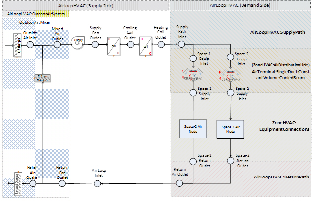
Passive Chilled Beams
General Description
Passive chilled beams are essentially bare chilled water coils which can either be recessed or suspended from the ceiling that rely on natural convection to transport warm air vertically to the beam location. The room air is then naturally drawn through the perforated ceiling over the top of the passive chilled beams, and the cooled air drops from the underside of the beam and cools the space. The passive chilled beams are supplemented by an all air system which takes care of ventilation as well as the latent load component.
Controlling Coil Setpoints
There are a number of ways to control the primary AHU’s cooling and heating coils. Usually, for this system, the main purpose of the primary AHU’s heating coil is only to preheat (if necessary) the return/OA mixture, (ROADB), to each time step’s economizer control point where the supply air dry bulb (SADB) is the temperature to satisfy either the control room’s cooling thermostat or the worst-case room’s cooling thermostat. (Remember: this system has a single AHU serving multiple rooms and so must decide which room or rooms to base its response on.) The purpose of the primary AHU’s cooling coil is to satisfy the ventilation cooling load plus the room latent load plus a portion (but not all) of the room(s) space cooling load.
To base the AHU’s response on a single room’s control thermostat, use “Supply air reset per single zone load” temperature control on the controls tab of the system properties and set the range of SADB from Design SADBC to Design room dry bulb in heating and define which room contains the control thermostat in the control zone field.
Alternatively, to base the AHU’s response on the worst-case cooling room, use the “Supply air reset per OA and worst case zone” temperature control with the same SADB range. Since the primary purpose of the main heating coil is to preheat, use a temperature controller to control the outlet of the primary AHU’s heating coil. So if the control thermostat is calling for a certain SADB, and the return/OA mixture is below SADB (minus fan heat), the main heating coil (located upstream of the main cooling coil) will preheat ROADB to SADB (minus fan heat).
For a draw-thru configuration, when the return/OA mixture is above SADB (minus fan heat), the cooling coil is activated to produce Cldbc=SADB-FanTD where Cldbc is the off cooling coil temperature and FanTD is the fan heat gain.
For a blow-thru configuration, when the return/OA mixture (plus fan heat) is above SADB, the cooling coil is activated to produce Cldbc=SADB. Alternatively, a “Supply air reset per single zone load” temperature control could be used at the supply air outlet to operate the primary AHU’s coils like a VTCV (variable temperature constant volume) system. Warning: fighting between the cooling and heating coils will occur between the primary AHU’s cooling and heating coils if proper temperature controls are not chosen or set up properly.
Another, perhaps more common method, is to use the “Supply air reset per OA” temperature control to change the primary AHU’s supply air setpoint depending on the outdoor temperature.
Sizing Considerations
The chilled beams handle only a portion of the room sensible load and none of the room latent since we don’t want condensation to occur on the chilled beams. Choosing the primary AHU’s cooling coil’s design SADBClg is tricky because the SADB in combination with a minimum airflow setting will determine the required capacity of the downstream chilled beams, i.e., the chilled beam capacity for a given room will equal the room space load minus whatever the central system supplies, i.e., DsnChBeamSensCapclg = DsnRmSpaceSensibleLoadclg - CpAir*RhoAir*DesAirVolFlow* (DsRmdbclg - DsnSADBClg).
If the primary job of the primary AHU’s heating coil is to preheat the supply air, then set Design SADBHtg equal to the design room heating dry bulb, DsRmdbhtg. If “Supply air reset per single zone load” temperature controller and was chosen then setting DsnSADBHtg = DsRmdbhtg will restrict the primary AHU’s main heating coil’s heating capacity so it can do little more than preheat the supply air; however, setting DsnSADBHtg to a value above DsRmdbhtg will give the primary AHU’s heating coil more capacity.
However, the baseboards – generally needed for the two-pipe chilled beam configuration, in the rooms will not know about how the primary AHU’s heating coil was sized and so the baseboard capacity will default to the design zone space sensible heating load. For a four-pipe beam configuration, a baseboard is generally not needed and so the heating capacity of the beam can be autosized correctly. If the primary AHU operates as a VTCV unit, the primary airflow can provide part of the space heating load directly but more often than not, the primary SADB is controlled by OA reset and/or the primary AHU may need to operate in direct dehumidification mode to prevent condensation on the chilled beams, and so the beam heating coil must also provide reheat capability.
To support worst case, the beam heating coil should autosize as FinalZoneSizing.DesHeatLoad + (reheat CoolBeam.MaxAirVolFlow from FinalSysSizing.CoolSupTemp to FinalZoneSizing.ZoneTempAtHeatPeak) and assume no space heating credit from the primary AHU subject to special sizing options on the chilled beam object.
Application Considerations
1. It is unwise to set the primary AHU’s sizing method to Ventilation Requirement for active chilled beams. The performance of the active chilled beams is directly tied to the amount of the primary airflow delivered to the chilled beams. Since the chilled beams are autosized according to the remainder of the room sensible load not met by the primary AHU, then the chilled beams may be either over- or under-aired and so be unable to operate properly. It is better to use a minimum flow rate input, e.g., 4 l/s/m2
2. To achieve proper room temperature control, the best practice is to create each primary AHU so its attached rooms have a similar façade (i.e. all walls facing same direction with similar proportion of glass). During annual operation, this allows the primary AHU to respond to a similar thermostat signal. It would be unwise, for example, for the primary AHU delivering air to a south-facing room in cooling mode while a north-facing room in the same zone requires heating. While the chilled beams or baseboard convectors in each room can respond as necessary to their remaining space sensible load, this is likely to waste energy.
3. During the annual energy simulation, the primary AHU of an active chilled beam system will reset its SADB depending on the choice of temperature control. If a cooling load still exists in some of the rooms, the chilled beams in those rooms will then operate to finish off any space sensible load not met by the primary AHU. However, the chilled beam controls will throttle back the chilled beam flow rate if they detect that condensation is about to begin on the chilled beams. Typically, this happens when the primary SADB is too high at a time when the room relative humidity is high and because the user has changed the humidity control from "Supply air reset per maximum” to “Supply air reset” or because the primary AHU’s average thermostat signal is not representative of the worst-case cooling room. If the chilled beams were forced to throttle back their capacity to avoid condensation, this can lead to unmet loads and overly warm room temps.
Displacement Ventilation
DV w/ Passive Chilled Beams
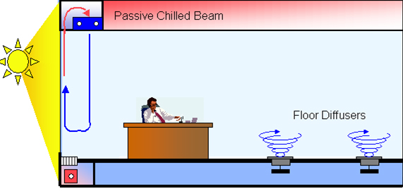
Ventilation and dehumidification of the space is accomplished by underfloor diffusers served by a central constant volume AHU. The chilled beams should be selected to offset the heat gains associated with the perimeter exposure plus some portion of the occupant, equipment and lighting load. As these beams do not perform during heating operation, a low level hydronic (or electric resistance) heating system is assumed. This combination system (DV with passive beams) will tend to operate like a mixing system once the chilled beams begin to operate at a significant level.
DV w/ Room Induction
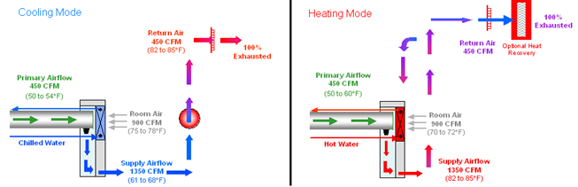
Primary air is delivered by a central air handler through the induction nozzles. The velocity of the nozzles induces room air through the integral heat transfer coil which is then cooled in accordance with space thermostat demands prior to mixing with the primary air. The use of room air induction and reconditioning allows the use of 100% outside air as the primary air source. This outside air is cooled to saturation at 50 to 54ºF within the air handling unit, then ducted to the induction terminals. Mixing with the reconditioned room air elevates the temperature of the air mixture to a level which is appropriate for displacement conditioning of the space. The space thermostat regulates the amount of induced air reconditioning in accordance with the room cooling requirements, resulting in a constant volume, variable temperature (61 to 68ºF) discharge to the room. During the heating mode, discharge air is warmer than room air and thus rises to create an air curtain along the perimeter windows. Only the minimum amount of terminals required to satisfy the space heating load should be fitted with four pipe coils. This way a maximum amount of supply air will continue to discharge in a displacement fashion. In heating mode the system operates much like a mixing ventilation system; however, this is not necessary bad from an energy standpoint, since a greater proportion of the internal loads stay in the “occupied” layer and thus offset more of the space heating load.
Heating Only
Each system type contains description of the system and its components.
Unit Heater
This system is created with the Unit Heater zone forced air piece of equipment. A separate unit heater, including air handler and heating coil, is located in each room. The design heating supply air temperature is assumed to be 95 F unless overridden by user input on the zone sizing tab of the system properties.
The supply fan follows the main heating fan schedule in a time-clock fashion, bringing in outside air through the main heating coil according to the ventilation schedule.
When the room drift temperature rises above the room heating thermostat, the heating coil is de-activated, allowing the space temperature to drift upward. Since the supply air will be at the return/outside air dry bulb temperature (plus fan heat), scheduling outside air into the space will temper this effect to some degree.
When the room drift temperature drops below the room heating thermostat, the heating coil is modulated to produce a supply air dry bulb that will bring the room temperature up to the heating thermostat temperature.
System Options
1. The value of minimum ventilation airflow will be proportional to the percentage defined by the outside air schedule. The value of outside airflow may be greater than the nominal value if an economizer is activated.
The value of outside airflow may be less than the nominal ventilation value if the supply has been scheduled at less than 100%; the outside air percentage for a particular hour will be multiplied by the main heating fan utilization percent for that hour. If the supply fan has been scheduled off for a particular hour, no outside air can be delivered to the rooms.
2. Supply Fan Controls: The supply fan is controlled in time clock fashion, i.e., if the schedule reads 80% for a particular hour, the fan will operate at full rpm for 80% of the hour and remain off the rest of the hour. Since the supply fan delivers conditioned air to the space, reducing the percent it can operate during a given hour will cause the heating coil to modulate at a higher supply air temperature during the percent of the hour the fan is available. If the fan is not allowed to operate long enough, the room temperature will be allowed to drift, the amount dependent on the magnitude of the unmet space load.
Application Notes
● If the ventilation air is brought in through a separate ventilation system, a zone direct DOA should be used. Economizer controls are not available to the standard UV system; however, opening and shutting of windows can be simulated (even if there are no external walls) by specifying a dry bulb economizer type and scheduling the economizer available during occupied hours.
● If the heating fan is to be cycled during unoccupied hours, enter fan cycling on the availability manager tab of the system properties.
● Internal rooms (rooms with no walls, roofs, etc.) should be provided with adequate outside air if internal loads are scheduled; otherwise, the room temperature may go out of control.
● Since the ventilation air brought into the space will create "positive" building pressure, it is suggested that infiltration be scheduled opposite the outside air schedule, e.g., for outside air scheduled at 40% for a particular hour, the infiltration schedule should read (100-40) = 60%.
Ventilation and Heating
This system is created with the Unit Ventilator zone forced air piece of equipment. A separate unit heater, including air handler and heating coil, is located in each room. The design heating supply air temperature is assumed to be 95 F unless overridden by user input on the zone sizing tab of the system properties.
The supply fan follows the main heating fan schedule in a time-clock fashion, bringing in outside air through the main heating coil according to the ventilation schedule.
When the room drift temperature rises above the room heating thermostat, the heating coil is de-activated, allowing the space temperature to drift upward. Since the supply air will be at the return/outside air dry bulb temperature (plus fan heat), scheduling outside air into the space will temper this effect to some degree.
When the room drift temperature drops below the room heating thermostat, the heating coil is modulated to produce a supply air dry bulb that will bring the room temperature up to the heating thermostat temperature.
System Options
1. The value of minimum ventilation airflow will be proportional to the percentage defined by the outside air schedule. The value of outside airflow may be greater than the nominal value if an economizer is activated.
The value of outside airflow may be less than the nominal ventilation value if the supply has been scheduled at less than 100%; the outside air percentage for a particular hour will be multiplied by the main heating fan utilization percent for that hour. If the supply fan has been scheduled off for a particular hour, no outside air can be delivered to the rooms.
2. Supply Fan Controls. The supply fan is controlled in time clock fashion, i.e., if the schedule reads 80% for a particular hour, the fan will operate at full rpm for 80% of the hour and remain off the rest of the hour. Since the supply fan delivers conditioned air to the space, reducing the percent it can operate during a given hour will cause the heating coil to modulate at a higher supply air temperature during the percent of the hour the fan is available. If the fan is not allowed to operate long enough, the room temperature will be allowed to drift, the amount dependent on the magnitude of the unmet space load.
Application Notes
● If the ventilation air is brought in through a separate ventilation system, a zone direct DOA should be used. Economizer controls are not available to the standard UV system; however, opening and shutting of windows can be simulated (even if there are no external walls) by specifying a dry bulb economizer type and scheduling the economizer available during occupied hours.
● If the heating fan is to be cycled during unoccupied hours, enter fan cycling on the availability manager tab of the system properties.
● Internal rooms (rooms with no walls, roofs, etc.) should be provided with adequate outside air if internal loads are scheduled; otherwise, the room temperature may go out of control.
● Since the ventilation air brought into the space will create "positive" building pressure, it is suggested that infiltration be scheduled opposite the outside air schedule, e.g., for outside air scheduled at 40% for a particular hour, the infiltration schedule should read (100-40) = 60%.
Cooling Only
Each system type contains description of the system and its components.
Computer Room Unit
The design is peak air and peak cooling capacity.
A separate computer room unit, including air handler and cooling coil, is assumed for each room. Each unit is located on the ROA deck and draws return air from a common return air plenum. The design cooling supply air temperature is determined from user input and cannot be overridden by outside air reset schedules. The fans are constant volume while the coils are cycled to meet the load.
System Simulation
The computer room system operates in a manner similar to the single zone (SZ) system except that it will control the room humidity between the design room relative humidity and the humidification minimum relative humidity. The system will dehumidify and supply air if the average room relative humidity is above the design room relative humidity. The system will humidify the supply air if the room relative humidity is below the humidification minimum relative humidity setpoint.
When the room drift temperature rises above the room cooling thermostat, the cooling coil is energized (at a constant cooling supply air temperature) for a percentage of the hour that it takes to bring the room temperature down to the cooling thermostat temperature. If further dehumidification is needed, the cooling coil is energized for a longer percentage of the hour. For the portion of the hour that the cooling coil is de-energized, the supply air will remain at the return/outside air dry bulb temperature (plus supply fan heat). If the humidistat detects that the average room relative humidity exiting through the room return air grilles falls below the relative humidity minimum setpoint, the supply air is humidified before being admitted to the space.
Under Floor Air Distribution (UFAD)
Each system type contains description of the system and its components.
|
|
|
|
|
|
UFAD VAV w/Baseboard Heating
This system is similar to a VAV system with baseboard heat, except that:
1. the supply air is delivered via an underfloor plenum and,
2. a return-air bypass arrangement is assumed in order to provide sufficient dehumidification without the need for reheat.
Because this system delivers air via an underfloor plenum, be sure to include a raised floor/underfloor plenum height when drawing the rooms that will be assigned to this system. At design cooling conditions, the supply air is delivered from floor diffusers at a warmer supply-air temperature (default = 65°F) and at a lower velocity than is typical for overhead delivery methods. Because the supply air is introduced from the pressurized floor plenum, a warmer supply-air temperature is necessary to avoid an uncomfortable temperature difference between ankle and head heights. A modulating damper varies the amount of air introduced to the room based on the space temperature sensor.
If the zone thermostat calls for heat, the damper is closed to minimum position, and a convector (located in a trench that is not open to the floor plenum) or baseboard heater (located above the raised floor) activates to add heat to the zone. For any underfloor air distribution system, the floor diffusers should be as close to the supply shaft as possible to minimize the heat gain as the cool supply air travels through the underfloor plenum.
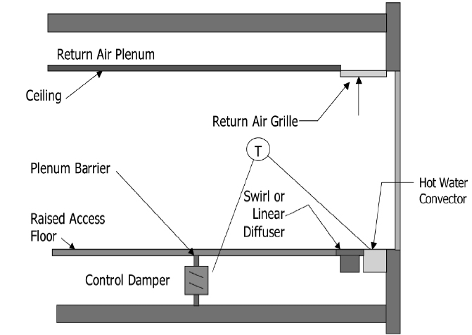
In this option, cooling and ventilation air are provided by the central system. As illustrated above, perimeter subdivisions of the plenum are created below each zone. A pressure-dependent modulating damper varies the amount of air introduced to the zone based on a space temperature sensor. In heating, the damper goes to minimum position and a convector in a trench that is not open to the plenum, or a baseboard heater located above the raised floor, engages to add heat to the zone.
UFAD VAV w/ Fan-Assisted Reheat
This system is similar to a VAV Reheat (VRH) system, except that:
1. the supply air is delivered via an underfloor plenum,
2. a return-air bypass arrangement is assumed in order to provide sufficient dehumidification without the need for reheat, and
3. space heating is supplied by an underfloor terminal that uses a small fan (Secondary Fan) to draw air from the floor through a heating coil.
Because this system delivers air via an underfloor plenum, be sure to include a raised floor/underfloor plenum height when drawing the rooms that will be assigned to this system. At design cooling conditions, the supply air is delivered from floor diffusers at a warmer supply-air temperature (default = 65°F) and at a lower velocity than is typical for overhead delivery methods. Because the supply air is introduced from the pressurized floor plenum, a warmer supply-air temperature is necessary to avoid an uncomfortable temperature difference between ankle and head heights.
If the zone thermostat calls for heat, the Secondary Fan activates and draw air from the floor plenum through the terminal heating coil. The static pressure and energy rate for this terminal fan are entered as the Secondary Fan on the Create Systems – Fan Overrides screen. To delete this terminal fan, select “Shutoff VAV” from the VAV Minimum Type drop-down list (Create Rooms – Airflows screen). For any underfloor air distribution system, the floor diffusers should be as close to the supply shaft as possible to minimize the heat gain as the cool supply air travels through the underfloor plenum.
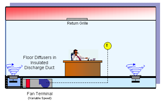
This is an illustration of a fan terminal discharging into an insulated discharge duct feeding several floor outlets that condition the perimeter. Perimeter space heating may be incorporated in the form of reheat coils within these terminals or may utilize a separate fin tube coil located in the discharge plenum. As this terminal has no provision for the induction of room air, it will likely incorporate a variable speed motor to adjust the airflow delivery in response to space thermostat requirements.
UFAD CV
This system is similar to a Variable-Temperature, Constant-Volume (VTCV) system, except that:
1. the supply air is delivered via an underfloor plenum,
2. a return-air bypass arrangement is assumed in order to provide sufficient dehumidification without the need for reheat, and
3. space heating is supplied by a baseboard radiator or convector.
Because this system delivers air via an underfloor plenum, be sure to include a raised floor/underfloor plenum height when drawing the rooms that will be assigned to this system. At design cooling conditions, the supply air is delivered from floor diffusers at a warmer supply-air temperature (default = 65°F) and at a lower velocity than is typical for overhead delivery methods. Because the supply air is introduced from the pressurized floor plenum, a warmer supply-air temperature is necessary to avoid an uncomfortable temperature difference between ankle and head heights. As the room sensible cooling load decreases, the capacity of the main cooling coil will be reduced, resulting in a warmer supply-air temperature.
The main heating coil is combined with the preheat coil in the main air handler and can be used to provide morning warmup. If the zone thermostat calls for heat, the main heating coil will condition the supply air to the design room heating thermostat setpoint and the baseboard radiator or convector is activated to satisfy the space heating load. Since the main cooling and heating coils are located at the zone level, it is important to assign rooms that have similar thermal load characteristics to the same zone. For any underfloor air distribution system, the floor diffusers should be as close to the supply shaft as possible to minimize the heat gain as the cool supply air travels through the underfloor plenum.
In order to provide a certain amount of dehumidification without the need for reheat, a return air bypass arrangement is assumed, e.g., outside air is mixed with recirculated return air, then cooled to saturation at 53-54˚F in order to remove an adequate amount of moisture from the air stream. A portion of the return air is introduced downstream of the coil and mixed with the saturated mixture to achieve the higher discharge air temperature.
UFAD PFPVAV
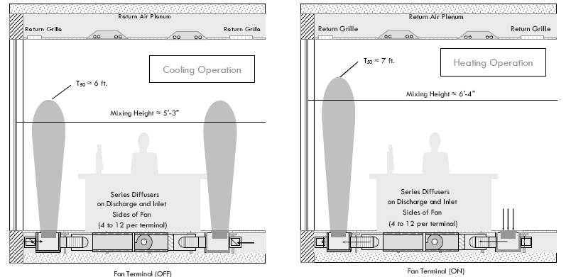
Cool air (from the pressurized supply plenum) is modulated by dampers within the diffuser terminals (on the inlet and discharge side) according to the space cooling demand, while the fan terminal remains off. Upon a further drop in space temperature, the dampers close and the integral fan and heating coil is energized. The diffusers on the inlet side of the fan become return inlets while those on the discharge supply a constant volume of reheated air to the space. Room air conditions are slightly stratified, but mixed conditions exist to approximately 6 foot level during design cooling and heating operation, negating most displacement advantages.
Because this system delivers air via an underfloor plenum, be sure to include a raised floor/underfloor plenum height when drawing the rooms that will be assigned to this system.
This perimeter system option consists of essentially an overhead VAV system placed under the floor in the raised-floor plenum. In general, this approach does not take advantage of the plenum as a low-pressure air distribution pathway, and the large amount of equipment and ducts placed in the plenum severely limit the flexible use of the plenum space. This system option is usually employed with conventional 55°F (13°C) supply air temperature and can be necessary if envelope loads are high, particularly solar loads. In the case of high envelope loads, the 63-65°F (17-18°C) supply air temperature typical of UFAD systems may be too warm to effectively remove the loads. This underfloor conventional VAV system using 55°F (13°C) air or colder can deal with high loads. The system efficiency and cost of this option is comparable to standard OH systems, though taken together with the cost of the raised floor it can be an expensive choice
UFAD SFPVAV
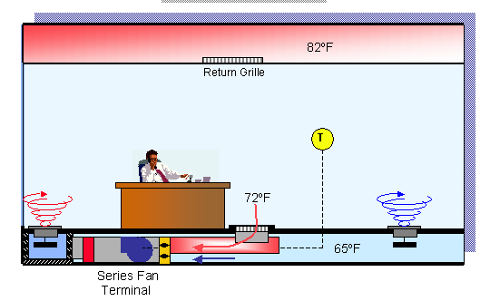
In this configuration the fan box intake is fitted with a damper that allows air to be taken from the room in heating mode or from the plenum in cooling mode. As cooling demand varies, either room air or hot-water reheat is used to temper the cooling supply air delivered to the space. In heating mode, the intake damper goes to a minimum position to allow minimum ventilation while the remaining air comes from recirculated room air. Heat is added via the reheat coil as needed. Room air conditions are slightly stratified, but mixed conditions exist to approximately 6 foot level during design cooling and heating operation, negating most displacement advantages.
Because this system delivers air via an underfloor plenum, be sure to include a raised floor/underfloor plenum height when drawing the rooms that will be assigned to this system.
Displacement Ventilation (DV)
If supply/ventilation air is introduced from the floor or a wall near the floor at certain velocities, a plume is assumed to form around the people or miscellaneous equipment load. A portion of the sensible heat may then travel upward (rather than be uniformly mixed as generally happens for overhead supply configurations), causing thermal stratification to occur in a manner similar to that shown in the figure below.
Because this system delivers air via an underfloor plenum, be sure to include a raised floor/underfloor plenum height when drawing the rooms that will be assigned to this system. Since a portion of the space sensible loads are shifted to the upper stratified layer, this allows for a reduction of the space sensible load used to calculate the cooling supply airflow rates when compared to an overhead system which assumes a fully mixed condition. However, the cooling airflow itself may not decrease (and might even increase) since higher cooling supply air dry bulbs are typically used with this configuration. Perimeter zones differ from interior zones in type and magnitude of heated thermal plumes. In perimeter zones, the dominant plume occurs vertically at windows, and, under peak load conditions, can be several times greater in magnitude than the total internal heat gains.
During a full simulation, the program will check whether conditions each time step actually produce temperature stratification for a particular room. For example, if the supply air is warmer than the room air, the driving force for the convective plumes will not be present. Similarly, if the room is not occupied and has low internal heat gains, the driving force that causes the heat to rise towards the ceiling exhaust will not affect the flow pattern. Chilled ceiling panels or passive chilled beams that supplement the cooling capacity of displacement ventilation or UFAD systems will create downdrafts in the occupied portion of the space, thus reducing the amount of convective fraction that goes to the upper stratified layer. For any hour that these conditions occur the program assumes that stratification does not occur and the associated room air is fully mixed.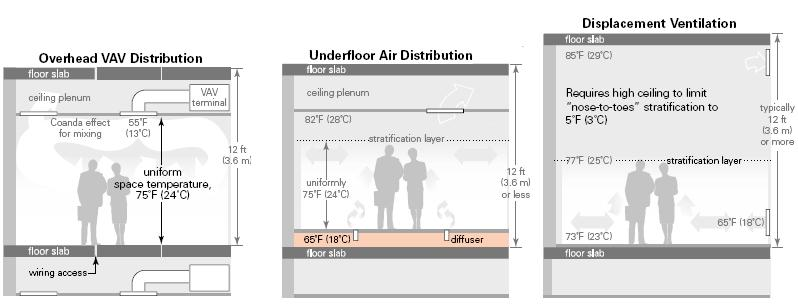
Each system type contains description of the system and its components.
Displacement Vent CV
The supply air delivered from the sidewall diffusers is delivered at a higher supply air temperature and lower velocity than is typical for overhead mixing and non-DV underfloor systems. In order to provide a certain amount of dehumidification without the need for reheat, a return air bypass arrangement is assumed, e.g., outside air is mixed with recirculated return air, then cooled to saturation at 55-58˚F in order to remove an adequate amount of moisture from the air stream. A portion of the return air is introduced downstream of the coil and mixed with the saturated mixture to achieve the higher discharge air temperature.
Because this system delivers air via an underfloor plenum, be sure to include a raised floor/underfloor plenum height when drawing the rooms that will be assigned to this system.
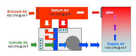
A portion of recirculation air is mixed with outside air, then the mixture is subcooled to a saturation temperature (52 to 55°F) to remove sufficient moisture. This air stream is then mixed with the remaining recirculated air (bypassed around the coil) which results is a discharge mixture at the desired temperature and humidity ratio for the space.
Displacement Vent VAV
The supply air delivered from the sidewall diffusers is delivered at a higher supply air temperature and lower velocity than is typical for overhead mixing and non-DV underfloor systems. In order to provide a certain amount of dehumidification without the need for reheat, a return air bypass arrangement is assumed, e.g., outside air is mixed with recirculated return air, then cooled to saturation at 55-58˚F in order to remove an adequate amount of moisture from the air stream. A portion of the return air is introduced downstream of the coil and mixed with the saturated mixture to achieve the higher discharge air temperature. Choosing supply air reset via supply air reset schedule will increase the efficiency of the system. Space heating/reheat defaults to baseboard convectors but can be changed to ceiling, underfloor, or wall-mounted fan coils
Because this system delivers air via an underfloor plenum, be sure to include a raised floor/underfloor plenum height when drawing the rooms that will be assigned to this system.
DV w/ Chilled Ceilings
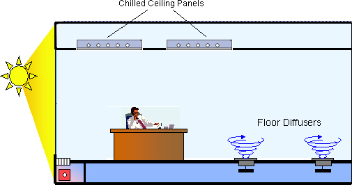
Ventilation and dehumidification of the space is accomplished by underfloor diffusers served by a central constant volume AHU. Building skin cooling loads are handled by the use of chilled ceiling panels placed into the dropped ceiling. The chilled ceiling panels should be selected to offset the heat gains associated with the perimeter exposure plus some portion of the occupant, equipment and lighting load. As these beams do not perform during heating operation, a low level hydronic (or electric resistance) heating system is assumed.
Because this system delivers air via an underfloor plenum, be sure to include a raised floor/underfloor plenum height when drawing the rooms that will be assigned to this system.
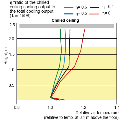
It is generally acknowledged that the space temperature can be maintained some 2 to 3°F warmer when chilled ceilings are used due to their radiant effect which is not measured by normal space temperature sensors. However, this combination system (DV with chilled ceiling) will tend to operate more like a mixing system as the chilled ceiling output increases.
Outdoor Air System (DOA)
Outdoor air units are placed in the outdoor air path and condition only the ventilation air. DOAs can be created in the system library and applied on the Configure Systems tab of the Systems section in the project. There are a number of different DOA types that can be created and applied to different systems in the project.
A note on temperature control for DOA systems:
When the temperature controller is set to Temperature Setpoint, it is best to use a separate temperature controller for each coil.
If a DOA system uses one temperature controller connected to both the cooling coil and heating coil, the DOA will control to the DOAS Supply Air Dry Bulb Cooling temperature in both cooling and heating modes. If a separate temperature controller is used for the cooling and heating coils, the DOA will condition to the DOAS Supply Air Dry Bulb Cooling in cooling mode and the DOAS Supply Air Dry Bulb Heating in heating mode. These temperatures are defined on the Sizing tab of the DOAS properties.
When the temperature controller is set to any of the Supply air temperature reset options, it is best to use one temperature controller connected to both the cooling and heating coils.
If a DOA system uses one temperature controller connected to both the cooling coil and heating coil, the DOA will reset between the DOAS Supply Air Dry Bulb Cooling temperature and DOAS Supply Air Dry Bulb Heating temperature. If a separate temperature controller is used for the cooling and heating coils, the DOA will condition to the DOAS Supply Air Dry Bulb Cooling in cooling mode and the DOAS Supply Air Dry Bulb Heating temperature in heating mode without resetting between those two temperatures.
Zone DOA
The Zone DOA will deliver conditioned outside air directly to a zone. Each zone on a system with a Zone DOA will have its own individual DOA unit.
Zone Neutral Control
The Neutral Temperature DOA will conditioned the outside air to zone neutral conditions. The DOA will attempt to minimize the ventilation load on the zone by delivering air at the same setpoint conditions as the zone.
Zone Temperature Control
The Temperature Control DOA will deliver ventilation air at a heating temperature setpoint, cooling temperature setpoint, or within the deadband between the cooling and heating temperature setpoints.
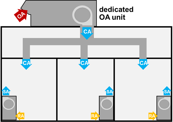
Single System DOA
The Single System DOA will deliver conditioned outside air at the system level. One DOA unit will serve all of the zones assigned to one particular system. The conditioned outdoor air will be delivered to the system just before the main system coils.
If the system is a zone level system such as a packaged terminal air conditioner (PTAC), each zone on that system will get its own PTAC. When a Single System DOA is used, one DOA will serve each of the PTAC units.
System Cool/Heat
A DOA unit conditions ventilation airflow to the user entered cooling and heating supply air dry bulb temperature. The air is delivered at the system level to one system.
System Dehum/Cool or Heat
A DOA unit delivers conditioned outdoor air at a user-specified low humidity ratio dehumidifying the supply airflow without reheating it. The air is delivered at the system level to one system.
System Dehum and Reheat
A DOA unit delivers conditioned outdoor air at a “neutral” temperature by dehumidifying the outdoor air to a user-specified low humidity ratio and then reheating it to a user-specified dry bulb that is near the room temperature. The air is delivered at the system level to one system.
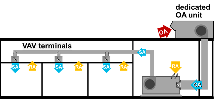
Multiple System DOA
The Multiple System DOA will deliver conditioned outside air to multiple systems using just one DOA unit. At this time, this is only valid for zone level system types.
Multi Sys Cool/Heat
A DOA unit conditions ventilation airflow to the user entered cooling and heating supply air dry bulb temperature. The air is delivered at the system level to multiple systems.
Multi Sys Dehum/Cool or Heat
A DOA unit delivers conditioned outdoor air at a user-specified low humidity ratio dehumidifying the supply airflow without reheating it. The air is delivered at the system level to multiple systems.
Multi Sys Dehum and Reheat
A DOA unit delivers conditioned outdoor air at a “neutral” temperature by dehumidifying the outdoor air to a user-specified low humidity ratio and then reheating it to a user-specified dry bulb that is near the room temperature. The air is delivered at the system level to multiple systems.
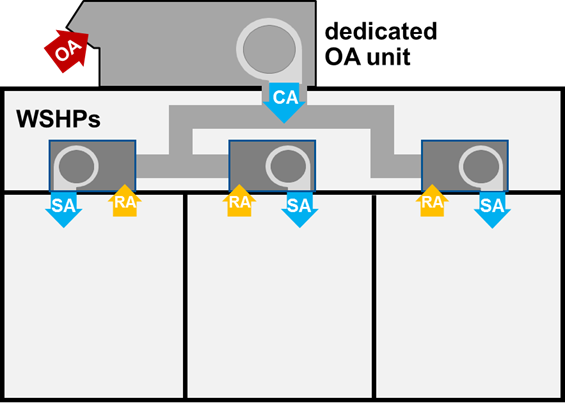
Ventilation Only System
The ventilation only system is a 100% outdoor air system and works like a non-mechanical ventilation system. Unconditioned outdoor air will be brought into all of the zones assigned to this system. Unlike the other DOA system types, the ventilation only system will be available in the Select Systems section, not the Add DOA section on the Configure Systems tab because this is a standalone system.
90.1 Systems
This category contains all the systems outlined in ASHRAE 90.1 Table G3.1.1B used for modeling 90.1 baseline systems.
|
ASHRAE System
|
Fan Config-uration
|
Return Air Path
|
Cooling Coil Location
|
Econo-mizer
|
Energy Recovery
|
Optimum Start
|
Supply Air Reset
|
Primary
|
Secondary
|
Over-sized
|
Min Stop
|
|
1
|
Blow Thru
|
Room Direct
|
Room
|
Not Required
|
User input, if required
|
Yes
|
Not Required
|
FC Centrifugal CV
|
Not required
|
Yes
|
N/A
|
|
2
|
Blow Thru
|
Room Direct
|
Room
|
Not Required
|
User input, if require
|
Yes
|
Not Required
|
FC Centrifugal CV
|
Not required
|
Yes
|
N/A
|
|
3
|
Draw Thru
|
Plenum
|
Zone
|
User input, if required
|
User input, if require
|
Yes
|
Not Required
|
FC Centrifugal CV
|
Not required
|
Yes
|
N/A
|
|
4
|
Draw Thru
|
Plenum
|
Zone
|
User input, if required
|
User input, if require
|
Yes
|
Not Required
|
FC Centrifugal CV
|
Not required
|
Yes
|
N/A
|
|
5
|
Draw Thru
|
Plenum
|
System
|
User input, if required
|
User input, if require
|
Yes
|
Yes
|
90.1 Min VAV AF Centrifugal
|
Not required
|
Yes
|
0.4 cfm/sq ft
|
|
6
|
Draw Thru
|
Plenum
|
System
|
User input, if required
|
User input, if require
|
Yes
|
Yes
|
90.1 Min VAV AF Centrifugal
|
Parallel fan-powered VAV
|
Yes
|
30% cooling airflow
|
|
7
|
Draw Thru
|
Plenum
|
System
|
User input, if required
|
User input, if require
|
Yes
|
Yes
|
90.1 Min VAV AF Centrifugal
|
Not required
|
Yes
|
0.4 cfm/sq ft
|
|
8
|
Draw Thru
|
Plenum
|
System
|
User input, if required
|
User input, if require
|
Yes
|
Yes
|
90.1 Min VAV AF Centrifugal
|
Parallel fan-powered VAV
|
Yes
|
30% cooling airflow
|
|
9
|
Blow Thru
|
Room Direct
|
N/A
|
Not required
|
Not Required
|
Yes
|
Not Required
|
N/A
|
FC Centrifugal CV
|
Yes
|
N/A
|
|
10
|
Blow Thru
|
Room Direct
|
N/A
|
Not required
|
Not Required
|
Yes
|
Not Required
|
N/A
|
FC Centrifugal CV
|
Yes
|
N/A
|
Library dropdown
The Library dropdown allows the user to navigate to a different library such as the equipment library or materials library.
Search Library
The search window allows the user to search for a specific library member by name.