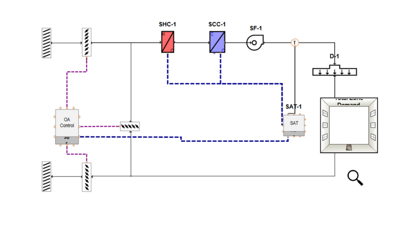
System Diagram
System Diagram
The diagram is the main working pane of the systems library. The diagram contains the air path and images of all of the components, terminal device, zone equipment, and controls that are used in the system.
When creating a system, it is good to remember that the system will be applied to all the zones, so making a system that is the lowest common denominator will allow for further customizing in the Zone equipment section in the project. This will allow different terminal devices or zone equipment to be used in specific zones instead of all of the zones on the system.

Air Path
The air path indicates the flow of air from component to component. The air path shows the direction of the air and how the air path combines and separates. Whenever a component is added to the airpath, a button will indicate where on the air path that component can be placed.
Zone
The zone represents the space that will be conditioned by the system. Zone level equipment will be placed in the zone on the diagram.
Controller connection lines
The controllers need to be connected to the components that they will control. These connections will be displayed as connection lines on the diagram. The temperature controller needs to be connected to both the outdoor air controller and the coils in the air path. If there is a humidity controller it should be connected to the components as well. Components that can be controlled by multiple controllers will have multiple ports where the controller can be connected.
Louvers and Dampers
Louvers and dampers represent points where the flow can be decreased or shut off completely. These come with the system diagram and may not be moved or removed.