Window Placement Tools
Window Placement Tool displays an icon for each door form factor (single, array, and band). The assembly construction (construction, overhangs, fins, shading control, etc.) of interior and exterior windows are defined in the theme and may be edited in the Room Properties>Construction for each door.
-
A window can be placed using a specific construction using the Edit Button in the toolbar in Window Library prior to placement.
-
All window types use the Elevation field to denote the distance from the slab to the bottom of the window.
Single Window
Place single window on a wall. To exit this tool, press the escape key or select another tool.

Array Window
Place more than one single window of the same width and height on a single or across multiple walls. To exit this tool, press the escape key or select another tool.

Quantity
Enter the number of windows in the array.
|
Default: 2
|
|
Typical Range: 2 to 10
|
|
Min Max: 2 to 100
|
|
Units: NA
|
Spacing
|
Default: Width of selected window
|
|
Typical Range: 24 to 60 inches (610 - 1524 mm)
|
|
Min Max: Min: 0 inches or mm; Max: NA
|
|
Units: inches, mm
|
Input Considerations:
Array of windows will be placed only when all can be placed on the wall(s). All windows must fit on the wall and no individual window surface in the array may cross an intersecting wall.
Band Window
Place a window that fills the horizontal area of a wall with a uniform specified % of wall area, or specified uniform height.

Height/Percent Glazing Numeric Input
Enter the height or % of occupiable wall area to be filled by a window that spans the entire length of a wall.
|
Default: 30
|
|
Typical Range: 2 to 10
|
|
Min Max: 1 to 100
|
|
Units: NA
|
Height/Percent Glazing Unit Input
Select either % or inches for Settings > Regional > Units = IP (mm for Settings > Regional > Units = SI)
Elevation
Specify the elevation from the slab at which the window is to be placed. This value is with respect to the active level. The bottom of the window is placed at the elevation specified.
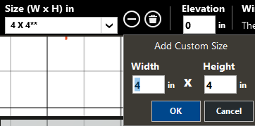
Add Custom Size
Add a custom size using the Plus Icon to the right of the list of sizes.

Enter a new custom size in this dialogue to include doors per design documents, when not included in standard sizes.
Each custom size is specific to the door or window Type selected and are saved with the project file.
Width, Height
Inputs represent the width and height of window being placed on the wall.
|
Default: 4 inches (300 mm)
|
|
Typical Range: 24 to 90 inches (610 - 2286 mm)
|
|
Min Max: Min: 4 inches (300 mm); Max: NA
|
|
Units: inches, mm
|
Delete Custom Size
With a custom size selected, use the Delete Icon to remove custom size from the list. It will no longer appear within the size list.
Standard TRACE sizes may not be deleted.
Input Considerations:
-
Place doors prior to band windows – doors cannot be placed inside band window area or within any existing windows.
-
Percent glazing input results in window filling entered percentage of occupiable space wall, and does not include plenum.
-
Band windows filling 100% of wall area will be shrunk by 1mm on each edge, so area will not be exact.
-
When percent is greater than what can fit on the wall because the elevation doesn’t allow, elevation is ignored.
-
The Numeric Input field hold the value input when units are changes, unless input would be invalid.
-
For values higher than 100 units, on change to %, input will be updated to 100.
-
Elevation input considers raised floor and drop ceiling. If window conflicts with plenum, invalid cursor is displayed and window may not be placed.For example: When Raised Floor exists, a window may not be a placed at elevation = 0.
-
To place windows in upper levels of NonStandard Rooms, activate the lowermost level of the NonStandard room and enter the absolute elevation of the window.
-
The wall area reported in Room Properties and in the Entered Values Report is the gross area of the wall – windows and doors are NOT subtracted from this area.