Trace 3D Plus
User Guide
 
×


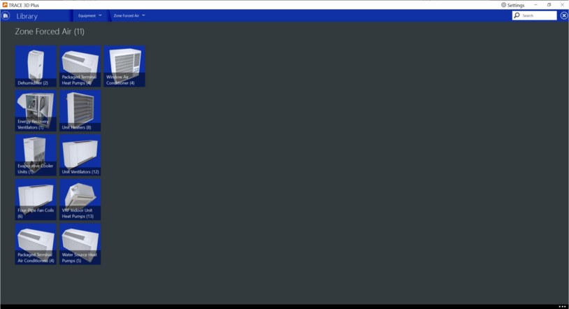
Zone Forced Air
In the zone forced air section of the library, zone force air library members can be viewed, modified, or created for use in a TRACE project file.
The following zone forced air types are available:


Dehumidifier
Content: These objects calculate the performance of zone (room) air dehumidifiers. They are meant to model conventional direct expansion (DX) cooling-based room air dehumidifiers (reject 100% of condenser heat to the zone air), but these objects might be able to be used to model other room air dehumidifier types.
Note: Standard TRACE library members cannot be modified or deleted but they can be copied and edited.
 
 
Product Tab
Rated Energy Rate
Default: 0
Typical Range: 0.49 – 1.11
Min Max: 0 to 1,000,000,000,000,000 (this field cannot be left blank)
Units: gal/kWh; L/kWh
This numeric input is the energy factor (i.e. liters of water removed per kWh of electricity consumed) at rated conditions (air entering the dehumidifier at 26.7°C [80°F] dry-bulb and 60% relative humidity, and air flow rate as defined by field “Rated Air Flow Rate” below). This is a required input field and the entered value must be greater than zero.
 
Rated Air Flow Rate
Default: 0
Typical Range: N/A
Min Max: 0 to 1,000,000,000,000,000 (this field cannot be left blank)
Units: L/s; cfm; m3/s; m3/hr
This numeric input is the volumetric air flow rate through the dehumidifier at rated conditions (air entering the dehumidifier at 26.7°C [80°F] dry-bulb and 60% relative humidity).  This is a required input field and the entered value must be greater than zero.
 
Rated Water Removal
Default: 0
Typical Range: 1 to 6 gal/day
Min Max: 0 to 1,000,000,000,000,000 (this field cannot be left blank)
Units: gal/day; L/day
This numeric input is the full load water removal rate for this object at rated conditions (air entering the dehumidifier at 26.7°C [80°F] dry-bulb and 60% relative humidity, and air flow rate as defined by the field “Rated Air Flow Rate”). This is a required input field and the entered value must be greater than zero.
 
Parasitic Electric Load
Default: 0
Typical Range: N/A
Min Max: 0 to 1,000,000,000,000,000 (this field cannot be left blank)
Units: W; hp; kW
This numeric input represents the parasitic electrical energy draw associated with this object.
 
Operational Limits
Maximum DB Limit
Default: 95°F
Typical Range: 85°F to 100°F
Min Max: 0 to 1,000,000,000,000,000 (this field cannot be left blank)
Units: °F; °C
This numeric field defines the maximum inlet air dry-bulb temperature for dehumidifier operation.
The dehumidifier will not operate if the inlet air temperature is above this value. This input value must be greater than the Minimum Dry-Bulb Temperature for Dehumidifier Operation, and the default value is 95°F.
 
Minimum DB Limit
Default: 50°F
Typical Range: 45°F to 60°F
Min Max: 0 to 1,000,000,000,000,000 (this field cannot be left blank)
Units: °F; °C
This numeric field defines the minimum inlet air dry-bulb temperature for dehumidifier operation.
The dehumidifier will not operate if the inlet air temperature is below this value. This input value must be less than the Maximum Dry-Bulb Temperature for Dehumidifier Operation, and the default value is 50°F.
 
 
Energy Recovery Ventilators
This compound component models a standalone energy recovery ventilator (ERV) that conditions outdoor ventilation air and supplies that air directly to a zone. The ERV unit is modeled as a collection of components: air-to-air heat exchanger, supply air fan, exhaust air fan and an optional controller to avoid overheating of the supply air (economizer or free cooling operation).
Note: Standard TRACE library members cannot be modified or deleted but they can be copied and edited.
 
 
People Based Rate
Default: 0 cfm/person
Typical Range: 0 to 20 cfm/person
Min Max: 0 to 1,000,000,000,000,000 (this field cannot be left blank)
Units: cfm/person; (m3/s)/person; (L/s)/person; (m3/hr)/person
This optional numeric field defines the ventilation rate per occupant in cubic meters per second per occupant. This field is only used when the supply and exhaust air flow rates are auto-sized.
 
Area Based Rate
Default: 0 cfm/ft2
Typical Range: 0 to 0.3
Min Max: 0 to 1,000,000,000,000,000 (this field cannot be left blank)
Units: cfm/ft2; (m3/s)/m2; (m3/hr)/per m2
This optional numeric field defines the ventilation rate per unit floor area in cubic meters per second per square meter. This field is only used when the supply and exhaust air flow rates are auto-sized.
 
Supply Fan
Supply Fan Type
Default: Constant Volume
Typical Range: N/A
Min Max: N/A
Units: N/A
This is the type of supply fan that is associated with the library member. Two options are available: Constant or Variable Volume.
 
Supply Air Fan
Default: Constant Volume Fan
Typical Range: N/A
Min Max: N/A
Units: N/A
This input selection refers to the name of the fan library member that is used in this object. 
 
Pressure Rise
Default: 4 inches H2O
Typical Range: 0.25 to 5 inches H2O
Min Max: 0 to 1,000,000,000,000,000 (this field cannot be left blank)
Units: inches H2O; lb/ft2; psig; Pa; kPa; mm Hg; mm H2O; bar; in Hg; atm; mm CE; m CE; m H2O; mbar
The value will be populated by default based on the fan library member selected.  You can override this value and the units of measure.
 
Fan Full Load Energy Rate
Default: 0.0002 kW/(cfm) ; Auto Size box is unchecked
Typical Range: 0.0001 to 0.0004 kW/(cfm)
Min Max: 0 to 1,000,000,000,000,000 (this field cannot be left blank)
Units: W; kW; W/(m3/sec); W/(m3/sec)-Pa; W/(cfm); W/(L/sec); W/(L/sec)-in H2O; kW/(cfm); kW/(L/sec); kW/(cfm)-in H2O; kW/(L/sec)-in H2O; W/(cfm)-in H2O; bhp
This checkbox indicates whether or not the full load energy rate used for the selected fan will be auto sized by the program or defined by the user.
 
Exhaust Fan
Exhaust Fan Type
Default: Constant Volume
Typical Range: N/A
Min Max: N/A
Units: N/A
This is the type of exhaust fan that is associated with the library member. Two options are available: Constant or Variable Volume.
 
Exhaust Air Fan
Default: Direct Drive Plenum Fan
Typical Range: N/A
Min Max: N/A
Units: N/A
This input selection refers to the name of the fan library member that is used for this object.
 
Pressure Rise
Default: 4 inches H2O
Typical Range: 0.25 to 5 inches H2O
Min Max: 0 to 1,000,000,000,000,000 (this field cannot be left blank)
Units: inches H2O; lb/ft2; psig; Pa; kPa; mm Hg; mm H2O; bar; in Hg; atm; mm CE; m CE; m H2O; mbar
The value will be populated by default based on the fan library member selected.  You can override this value and the units of measure.
 
Fan Full Load Energy Rate
Default: 0.0002 kW/(cfm) ; Auto Size box is unchecked
Typical Range: 0.0001 to 0.0004 kW/(cfm)
Min Max: 0 to 1,000,000,000,000,000 (this field cannot be left blank)
Units: W; kW; W/(m3/sec); W/(m3/sec)-Pa; W/(cfm); W/(L/sec); W/(L/sec)-in H2O; kW/(cfm); kW/(L/sec); kW/(cfm)-in H2O; kW/(L/sec)-in H2O; W/(cfm)-in H2O; bhp
This checkbox indicates whether or not the full load energy rate used for the selected fan will be auto sized by the program or defined by the user.
 
Heat Exchanger
Heat Exchanger Type
Default: Sensible and Latent
Typical Range: N/A
Min Max: N/A
Units: N/A
This input selection refers to the heat exchanger type used for this object. The only allowable type is Sensible and Latent.
 
Heat Exchanger
Default: Fixed-membrane Heat Exchanger
Typical Range: N/A
Min Max: N/A
Units: N/A
This input selection refers to the heat exchanger library member that is used for this object.
 
Economizer Control
Enable Economizer Mode
Default: None
Typical Range: N/A
Min Max: N/A
Units: N/A
This input selection refers to the type of operational controller that is used by this object. The following list of controller types are available to select: Fixed Dry Bulb, Fixed Enthalpy, Differential Dry Bulb, Differential Enthalpy, Fixed Dew Point and Dry Bulb, Differential Dry Bulb and Enthalpy.
 
Humidity Control
Enable Humidity Control
Default: No
Typical Range: N/A
Min Max: N/A
Units: N/A
This input selection refers to whether or not humidity control is used by this object when in operation. Allowable options are Yes or No.
 
 
Evaporative Cooler Units
The zone evaporative cooler unit is a compound object made up of a fan and one or two evaporative cooler components. This unit serves a single thermal zone as a forced-convection, cooling-only unit with supply fan. It always draws 100% of its supply air from the outside, passes the air through a supply fan and evaporative cooler(s) and then into the zone. The fan can be positioned upstream of the cooler(s) for a blow through placement. Or it can be positioned downstream of the cooler(s) for a draw through placement. If there is more than one evaporative cooler, then should be in series with the first cooler immediately upstream of the second cooler. There is an option to include a relief zone exhaust node to balance the air in the zone.
The unit can have either constant or variable speed fans. This zone unit differs from other constant speed forced-air zone units in that its controls are not based on a part-load formulation with averaged air flow rates. Instead the unit is completely on or off during the entire time-step. This means that it is beneficial to use relatively short time-steps. However for variable speed fans, the unit can modulate fan speed to just meet cooling loads and therefore operates similar to other zone HVAC units.
Note: Standard TRACE library members cannot be modified or deleted but they can be copied and edited.
 
 
Nominal Cooling Capacity
Default: Autosized box checked
Typical Range: N/A
Min Max: 0 to 1,000,000,000,000,000 (this field cannot be left blank)
Units: % Clg Capacity; W; kW; W/m2; W/ft2; tons; MW; Btuh; MBh
This checkbox indicates whether or not the capacity used for the selected fan will be auto sized by the program or referenced from the user defined input.
 
Supply Fan
Supply Fan Placement
Default: Blow Through
Typical Range: N/A
Min Max: N/A
Units: N/A
This selectable input field defines how the supply fan is arranged. There are two choices, Blow Through or Draw Through.  The Blow Through choice indicates that the fan is located upstream of the evaporative cooler(s). The Draw Through choice indicates that the fan is located downstream of the evaporative cooler(s). These are the only configurations that are available and the HVAC system nodes used as inlets and outlet in the components must be arranged consistent with the flow path.
 
Fan Control
Default: Cycling Fan - Load Setpoint
Typical Range: N/A
Min Max: N/A
Units: N/A
This field is used to determine how the unit is to be controlled. There are three possible choices:
1.      Cycling Fan – Zone Air Temperature: This control method determines whether or not to operate the cooler based on the thermostat setpoint and the zone air temperature. This thermostatic control method uses a throttling temperature range, defined in the Throttling Range input field, to model hysteresis-type control to avoid excessive short-cycling. If the zone air temperature is warmer than the cooling setpoint temperature plus one-half of the throttling range, then the unit is operated for the entire time-step at the design air mass flow rate. If the zone air temperature is cooler than the cooling setpoint temperature minus one-half of the throttling range, then the unit is off for the entire time-step. When the zone air temperatures are within the throttling range, then the unit will stay off if it was not running during the previous time-step and will stay on if it was already running. This control method does not usually behave in a smooth manner and zone conditions will tend to oscillate considerably during periods of low load.
2.      Cycling Fan – Load Setpoint: This control method determines whether or not to operate the cooler based on the predicted zone load to cooling setpoint. If there is a cooling load (and the unit is available), then the unit is operated for the entire time-step at the design air mass flow rate. If there is no cooling load, then the unit is not operated at all. The magnitude of the cooling load that will trigger the unit to operate can be controlled using the input Cooling Load Setpoint value. This control method does not usually behave in a smooth manner and zone conditions will tend to oscillate considerably during periods of low load.
3.      Variable Speed Fan – Load Setpoint: This control method determines whether or not to operate the cooler based on the predicted zone load to cooling setpoint. If there is a cooling load (and the unit is available), then the unit is operated for the entire time-step at a fan speed that is controlled to meet the sensible cooling load (if possible). The magnitude of the cooling load that will trigger the unit to operate can be controlled using the input Cooling Load Setpoint value. This control method requires a variable speed fan and cannot be used with the Constant Volume fan type.
 
Supply Fan Type
Default: Constant Volume
Typical Range: N/A
Min Max: N/A
Units: N/A
This is the type of supply fan that is associated with the library member. Two options are available: Constant or Variable Volume.
 
Supply Air Fan
Default: Direct Drive Plenum Fan
Typical Range: N/A
Min Max: N/A
Units: N/A
This input selection refers to the name of the fan library member that is used in this object.
 
Fan Full Load Energy Rate
Default: 0.0002 kW/(cfm); Auto Size box is unchecked
Typical Range: 0.0001 to 0.0004 kW/(cfm)
Min Max: 0 to 1,000,000,000,000,000 (this field cannot be left blank)
Units: W; kW; W/(m3/sec); W/(m3/sec)-Pa; W/(cfm); W/(L/sec); W/(L/sec)-in H2O; kW/(cfm); kW/(L/sec); kW/(cfm)-in H2O; kW/(L/sec)-in H2O; W/(cfm)-in H2O; bhp
This checkbox indicates whether or not the full load energy rate used for the selected fan will be auto sized by the program or referenced from the user defined input.
 
Pressure Rise
Default: 4 inches H2O
Typical Range: 0.25 to 5 in H2O
Min Max: 0 to 1,000,000,000,000,000 (this field cannot be left blank)
Units: in H2O; lb/ft2; psig; Pa; kPa; mm Hg; mm H2O; bar; in Hg; atm; mm CE; m CE; m H2O; mbar
The value will be populated by default based on the fan library member selected. You can override this value and the units of measure.
 
Dead Band Airflow
Default: Auto Size box checked
Typical Range: 0 to 25,000 cfm
Min Max: 0 to 1,000,000,000,000,000 (this field cannot be left blank)
Units: m3/sec; cfm; cfm/ft2; (m3/s)/m2; % Clg Airflow; % Htg Airflow; m3/hr-m2; L/s; m3/hr
 
Cooling Load Setpoint
Default: 0.028 tons
Typical Range: N/A
Min Max: 0 to 1,000,000,000,000,000 (this field cannot be left blank)
Units: W; kW; tons; Btuh; MBh
This input field defines the magnitude of a significant zone cooling load to use with zone-load-to-setpoint based control. This value is used when the unit’s control method is Cycling Fan – Load Setpoint or Variable Speed Fan – Load Setpoint. This is a sensible cooling load that is used as a threshold to determine when the cooling load is significant. When the predicted zone load to cooling setpoint is less than this threshold, the cooler unit’s control will consider the load to be too small to trigger operation.
 
 
Evaporative Cooler
Evaporative Cooler Type
Default: Direct Evaporative
Typical Range: N/A
Min Max: N/A
Units: N/A
This selectable field defines the type of evaporative cooler used in the unit. The zone evaporative cooler unit can have one or two separate cooler components and this field is for the first cooler. There are two types of evaporative cooler types to choose from: Direct Evaporative and Indirect Evaporative. 
 
Evaporative Cooler
Default: Test: East Data Center DEC
Typical Range: N/A
Min Max: N/A
Units: N/A
This input selection refers to the cooling coils library member that is used for this object.
 
Cooling Design Airflow
Default: Auto Size box checked
Typical Range: N/A
Min Max: 0 to 1,000,000,000,000,000 (this field cannot be left blank)
Units: m3/sec; cfm; cfm/ft2 (Floor); (m3/s)/m2 (Floor); % Clg Airflow; m3/hr-m2 (Floor); cm3/sec; m3/hr
This input refers to the design cooling airflow value associated with the evaporative cooler library member selected.  This input can be used to scale the capacity of the evaporative cooler as well. 
 
Optional Evaporative Cooler
Secondary Evaporative Cooler
Default: Blank
Typical Range: N/A
Min Max: N/A
Units: N/A
This input selection refers to the cooling coils library member that is used for this object.
 
Secondary Evaporative Cooler Type
Default: None
Typical Range: N/A
Min Max: N/A
Units: N/A
This selectable field defines the type of the second evaporative cooler used in the unit. The zone evaporative cooler unit can have one or two separate cooler components and this field is for the second cooler. There are 3 options to choose from.  The types of evaporative cooler types to choose from: Direct Evaporative and Indirect Evaporative.  None is the third option.
 
 
Four Pipe Fan Coils
This equipment is modeled as and in-room forced-convection hydronic unit. The hydronic heating coil may be replaced with an electric heating coil. Typically these units are small (200 – 1200 cfm) and self-contained. They are mostly used in exterior zones, usually in hotels, apartments, or offices. They may be connected to ducted outside air, or have a direct outside air vent, but they do not have outside air economizers. Units with outside air economizers are marketed (in the United States) as unit ventilators. Unit ventilators are typically bigger than fan coils and are widely used in classrooms or other applications where ventilation is a priority.
The heating or cooling output of the fan coil is controlled by varying the air flow rate, the water flow rate, or both. Air flow rate can be controlled by cycling the fan on/off or with a variable speed fan drive. The most common setup is a two or three speed fan with the speed selected by hand. The fan then cycles on/off to control heating / cooling output. The controls are often a wall mounted thermostat with hand selection of heating/cooling and fan speed (off/low/medium/high).
These controls may also be mounted on the unit.
Fan coil units with hydronic heat can instead be modeled using an electric heating coil if desired (i.e., replace the hydronic heating coil with an electric heating coil).
Note: Standard TRACE library members cannot be modified or deleted but they can be copied and edited.
 
 
Nominal Heating Capacity
Default: Auto Size box checked
Typical Range: 2 to 65 Mbh
Min Max: 0 to 1,000,000,000,000,000 (this field cannot be left blank)
Units: % Htg Capacity; W; kW; W/m2; W/ft2; tons; MW; Btuh; MBh; tons/ft2; Btuh/ft2
This checkbox indicates whether or not the capacity used for the selected heating coil will be auto sized by the program or referenced from the user defined input.
 
Nominal Cooling Capacity
Default: Auto Size box checked
Typical Range: 2 to 65 Mbh
Min Max: 0 to 1,000,000,000,000,000 (this field cannot be left blank)
Units: % Clg Capacity; W; kW; W/m2; W/ft2; tons; MW; Btuh; MBh; tons/ft2; Btuh/ft2
This checkbox indicates whether or not the capacity used for the selected cooling coil will be auto sized by the program or referenced from the user defined input. 
 
Supply Fan
Supply Fan Placement
Default: Blow Through
Typical Range: N/A
Min Max: N/A
Units: N/A
This selectable input field defines how the supply fan is arranged. There are two choices, Blow Through or Draw Through. The Blow Through choice indicates that the fan is located upstream of the coils. The Draw Through choice indicates that the fan is located downstream of the coils. These are the only configurations that are available and the HVAC system nodes used as inlets and outlet in the components must be arranged consistent with the flow path.
 
Capacity Control Method
Default: Multi-speed Cycling Fan with Constant Water Flow
Typical Range: N/A
Min Max: N/A
Units: N/A
This field is used to determine how the unit fan is to be controlled. There are four possible choices:
1.      Multi-speed Cycling Fan with Constant Water Flow: The fan speed is chosen so that the unit capacity is greater than or equal to the heating / cooling load and the fan is cycled to match unit output with the load.  The fan number of fan speeds is limited to a handful (1 – 3), as compared to the multiple speeds used in the Multi-speed Fan Cycling Speeds with Constant Water Flow control option.
Note: This capacity control method should only be used when the Supply Fan type selected is Constant Volume.
2.      Constant Flow Fan Variable Water Flow: The fan speed is held constant to produce a fixed air flow rate whenever the unit is scheduled on.  The hot water or chilled flow rate is varied so that the unit output matches the zone heating or cooling requirement.
Note: This capacity control method should only be used when the Supply Fan type selected is Constant Volume.
3.      Variable speed Fan Variable Water Flow: Both air and water flow rates are varied to match the load.
Note: This capacity control method should only be used when the Supply Fan type selected is Variable Volume.
4.      Variable speed Fan Constant Water Flow: The water flow rate is at full flow and the fan speed varies to meet the load.
Note: This capacity control method should only be used when the Supply Fan type selected is Variable Volume.
5.      Multi-speed Fan Cycling Speeds with Constant Water Flow:  The water flow rate is at full flow and the fan cycles between multiple set speeds to meet the load.
Note: This capacity control method should only be used when the Supply Fan type selected is Constant Volume.
6.      ASHRAE 90.1 Control: The fan air flow rate is reduced according to the low speed supply air flow ratio when the zone sensible load is less than the zone sensible load multiplied by the low speed supply air flow ratio. The water coil flow rate, or the electric heating coil part-load ratio, is modulated to meet the zone load. If the zone sensible load is greater than the zone sensible load multiplied by the low speed supply air flow ratio, then the air and water flow rate is increased to meet the load. If the zone load is greater than the design sensible load, the fan air flow rate is maintained at the maximum value while the water flow rate is further increased to the maximum available while electric heating coils are maintained at the maximum output.
 
Special Note: when the ASHRAE 90.1 VAV Fan is selected as the Supply Air Fan, if the Minimum Supply Air Temperature in Cooling/Heating Mode inputs are not specified, the simulation must include zone sizing to calculate the zone design sensible cooling and heating load used to modulate the fan speed and, for water coils, the water flow rate, or for electric heating coils, the part load ratio.
This control strategy is very similar to the reverse acting VAV control methodology used in TRACE™ 700. A schematic of this control strategy is provided below:
Note: This capacity control method can be used when the Supply Fan type selected is either Constant Volume or Variable Volume.
 
Supply Fan Type
Default: Constant volume
Typical Range: N/A
Min Max: N/A
Units: N/A
This is the type of supply fan that is associated with the library member. Two options are available: Constant or Variable Volume.
 
Supply Air Fan
Default: Direct Drive Plenum Fan
Typical Range: N/A
Min Max: N/A
Units: N/A
This input selection refers to the name of the fan library member that is used in this object.
 
Fan Full Load Energy Rate
Default: 0.0002 kW/(cfm); Auto Size box is unchecked
Typical Range: 0.0001 to 0.0004 kW/(cfm)
Min Max: 0 to 1,000,000,000,000,000 (this field cannot be left blank)
Units: W; kW; W/(m3/sec); W/(m3/sec)-Pa; W/(cfm); W/(L/sec); W/(L/sec)-Pa; kW/(cfm); kW/(L/sec); kW/(cfm)-in H2O; kW/(L/sec)-Pa; W/(cfm)-in H2O; bhp
This checkbox indicates whether or not the full load energy rate used for the selected fan will be auto sized by the program or referenced from the user defined input.
 
Pressure Rise
Default: 4 inches H2O
Typical Range: 0.25 to 5 in H2O
Min Max: 0 to 1,000,000,000,000,000 (this field cannot be left blank)
Units: inches H2O; lb/ft2; psig; Pa; kPa; mm Hg; mm H2O; bar; in Hg; atm; mm CE; m CE; m H2O; mbar
The value will be populated by default based on the fan library member selected.  You can override this value and the units of measure.
 
Low Speed Air Flow
Default: 33%
Typical Range: N/A
Min Max: 0 to 100%
Units: %
This numerical field specifies the low speed flow rate to the maximum supply air flow rate as a percentage. This value should be less than the Medium Speed Air Flow value. Leave this field blank if the capacity control method selected is not Cycling Fan.
 
Medium Speed Air Flow
Default: 66%
Typical Range: N/A
Min Max: 0 to 100%
Units: %
This numerical field specifies the medium speed flow rate to the maximum supply air flow rate as a percentage. This value should be greater than the Low Speed Air Flow value but less than 100%. Leave this field blank if the capacity control method selected is not Cycling Fan.
 
Dead Band Airflow
Default: Auto Size box checked
Typical Range: 200 to 1200 cfm
Min Max: 0 to 1,000,000,000,000,000 (this field cannot be left blank)
Units: m3/sec; cfm; cfm/ft2; (m3/s)/m2; % Clg Airflow; % Htg Airflow; m3/hr-m2; L/s; m3/hr
This numeric field defines the supply air flow rate leaving the fan coil when neither cooling nor heating is required (i.e. the cooling and heating coils are not operating). This field is only used when the fan coil supply air fan operating mode schedule specifies continuous fan operation.
If the air conditioner’s supply air fan operating mode schedule specifies continuous fan operation and this value is set to zero or this field is left blank, then the model assumes that the supply air flow rate when no cooling/heating is needed is equal to the supply air flow rate when the cooling or heating coil was last operating (for cooling operation or heating operation).
 
Unitary Cooling
Unitary Cooling Type
Default: Water (Detailed)
Typical Range: N/A
Min Max: N/A
Units: N/A
This field specifies the type of chilled water cooling coil to model for this fan coil unit.  Only two options are available to choose from: Water (Detailed) and Water (Simple)
 
Unitary Cooling
Default: 10 Row – Copper Fins – Prima Flo
Typical Range: N/A
Min Max: N/A
Units: N/A
This field allows you to select the cooling coil library member that will be used for this four pipe fan coil equipment.
 
Unitary Cooling Design Airflow
Default: Auto Size box checked
Typical Range: 200 to 1200 cfm
Min Max: 0 to 1,000,000,000,000,000 (this field cannot be left blank)
Units: m3/s; cfm; cfm/ft2; (m3/s)/m2; % Clg Airflow; cfm/ton; (m3/s)/(kW of Cooling Capacity); (m3/hr)/(kW of Cooling Capacity); (m3/s)/(W of Cooling Capacity); m3/hr ; m3/hr/m2; L/s; (L/s)(kW of Cooling Capacity)
This input refers to the design cooling airflow value associated with the four pipe fan coil library member. This input can be used to scale the size of the coil as well. 
 
Unitary Heating
Unitary Heating Type
Default: water
Typical Range: N/A
Min Max: N/A
Units: N/A
This field specifies the type of heating coil to model for this fan coil unit. Only two options are available to choose from: Water and Electric
 
Unitary Heating
Default: Water Heating Coil
Typical Range: N/A
Min Max: N/A
Units: N/A
This field allows you to select the heating coil library member that will be used for this four pipe fan coil equipment.
 
Unitary Heating Design Airflow
Default: Auto Size box checked
Typical Range: 200 to 1200 cfm
Min Max: 0 to 1,000,000,000,000,000 (this field cannot be left blank)
Units: cm3/s; m3/s; cfm; cfm/ft2; (m3/s)/m2; % Htg Airflow; cfm/ton; (m3/s)/(kW); (m3/hr)/(kW); (m3/s)/(W); m3/hr ; m3/hr/m2
This input refers to the design heating airflow value associated with the four pipe fan coil library member. This input can be used to scale the size of the coil as well.
 
 
Packaged Terminal Air Conditioners
The packaged terminal air conditioner (PTAC) is a compound object made up of other components. Each PTAC consists of an outdoor air mixer, direct expansion (DX) cooling coil, heating coil (gas, electric, hot water, or steam) and a supply air fan. PTACs can have draw through or blow through fan placement and can also be modeled by positioning the supply air fan between the outdoor air mixer and the DX cooling coil.
Note: Standard TRACE library members cannot be modified or deleted but they can be copied and edited.
 
 
Nominal Cooling Capacity
Default: Auto Size box checked
Typical Range: 7 to 19 Mbh
Min Max: 0 to 1,000,000,000,000,000 (this field cannot be left blank)
Units: % Clg Capacity; W; kW; W/m2; W/ft2; tons; Btuh; MBh; tons/ft2; Btuh/ft2
This checkbox indicates whether or not the capacity used for the selected cooling coil will be auto sized by the program or referenced from the user defined input.
 
Nominal Heating Capacity
Default: Auto Size box checked
Typical Range: 7 to 19 Mbh
Min Max: 0 to 1,000,000,000,000,000 (this field cannot be left blank)
Units: % Htg Capacity; W; kW; W/m2; W/ft2; tons; Btuh; MBh; tons/ft2; Btuh/ft2
This checkbox indicates whether or not the capacity used for the selected heating coil will be auto sized by the program or referenced from the user defined input. 
 
Supply Fan
Supply Fan Placement
Default: Blow through
Typical Range: N/A
Min Max: N/A
Units: N/A
This selectable input field defines how the supply fan is arranged. There are two choices, Blow Through or Draw Through.  The Blow Through choice indicates that the fan is located upstream of the coils. The Draw Through choice indicates that the fan is located downstream of the coils. These are the only configurations that are available and the HVAC system nodes used as inlets and outlet in the components must be arranged consistent with the flow path.
 
 
Cycling Mode
Default: Cycling fan
Typical Range: N/A
Min Max: N/A
Units: N/A
This field is used to determine how the unit fan is to be controlled. There are two possible choices:
1.      Cycling Fan: The fan speed is chosen so that the unit capacity is greater than or equal to the heating / cooling load and the fan is cycled to match unit output with the load.
2.      Continuous Fan: The fan speed is held constant to produce a fixed air flow rate whenever the unit is scheduled on.
 
Supply Fan Type
Default: Constant Volume
Typical Range: N/A
Min Max: N/A
Units: N/A
This is the type of supply fan that is associated with the library member.  Two options are available: Constant or Variable Volume.
 
Supply Air Fan
Default: Constant Volume Fan
Typical Range: N/A
Min Max: N/A
Units: N/A
This input selection refers to the name of the fan library member that is used in this object.
 
Fan Full Load Energy Rate
Default: 0.0002 kW/(cfm) ; Auto Size box is unchecked
Typical Range: 0.0001 to 0.0004 kW/(cfm)
Min Max: 0 to 1,000,000,000,000,000 (this field cannot be left blank)
Units: W; kW; W/(m3/sec); W/(m3/sec)-Pa; W/(cfm); W/(L/sec); W/(L/sec)-Pa; kW/(cfm); kW/(L/sec); kW/(cfm)-in H2O; kW/(L/sec)-Pa; W/(cfm)-in H2O; bhp
This checkbox indicates whether or not the full load energy rate used for the selected fan will be auto sized by the program or referenced from the user defined input.
 
Pressure Rise
Default: 4 inches H2O
Typical Range: 0.25 to 5 inches H2O
Min Max: 0 to 1,000,000,000,000,000 (this field cannot be left blank)
Units: in H2O; lb/ft2; psig; Pa; kPa; mm Hg; mm H2O; bar; in Hg; atm; mm CE; m CE; m H2O; mbar
The value will be populated by default based on the fan library member selected.  You can override this value and the units of measure.
 
Dead Band Airflow
Default: Auto Size box checked
Typical Range: N/A
Min Max: 0 to 1,000,000,000,000,000 (this field cannot be left blank)
Units: m3/sec; cfm; cfm/ft2; (m3/s)/m2; % Clg Airflow; % Htg Airflow; L/s; m3/hr; (m3/hr)/m2
This numeric field defines the supply air flow rate leaving the PTAC when neither cooling nor heating is required (i.e. the cooling and heating coils are not operating). This field is only used when the PTAC’s supply air fan operating mode schedule specifies continuous fan operation.
If the air conditioner’s supply air fan operating mode schedule specifies continuous fan operation and this value is set to zero or this field is left blank, then the model assumes that the supply air flow rate when no cooling/heating is needed is equal to the supply air flow rate when the cooling or heating coil was last operating (for cooling operation or heating operation).
 
Unitary Cooling
Unitary Cooling Type
Default: Air-cooled
Typical Range: N/A
Min Max: N/A
Units: N/A
This field specifies the type of DX cooling equipment that is to be modeled for this PTAC unit. Only one option is available: Air-Cooled.
 
 
Unitary Cooling
Default: 20 to 75 Ton High Eff VAV Packaged VS RTU
Typical Range: N/A
Min Max: N/A
Units: N/A
This field allows you to select the cooling coil library member that will be used for this PTAC equipment.
                                                                                                                                                                            
 
Unitary Cooling Design Airflow
Default: Auto Size box checked
Typical Range: 200 – 1200 cfm
Min Max: 0 to 1,000,000,000,000,000 (this field cannot be left blank)
Units: m3/s; cfm; cfm/ft2; (m3/s)/m2; % Clg Airflow; cfm/ton; (m3/s)/(kW of Cooling Capacity); (m3/hr)/(kW of Cooling Capacity); (m3/s)/(W of Cooling Capacity); m3/hr ; m3/hr/m2; L/s; (L/s)(kW of Cooling Capacity)
This input refers to the design cooling airflow value associated with the PTAC library member.  This input can be used to scale the size of the coil as well. 
 
Unitary Heating
Unitary Heating Type
Default: Electric
Typical Range: N/A
Min Max: N/A
Units: N/A
This field specifies the type of heating equipment to model for this PTAC.  Four options are available to choose from: Electric, Gas, Steam, Water.
 
Unitary Heating
Default: Electric Heating Coil
Typical Range: N/A
Min Max: N/A
Units: N/A
This field allows you to select the heating coil library member that will be used for this PTAC equipment.
 
 
Heating Design Airflow
Default: Auto Size box checked
Typical Range: 200 to 1200 cfm
Min Max: 0 to 1,000,000,000,000,000 (this field cannot be left blank)
Units: cm3/s; m3/s; cfm; cfm/ft2; (m3/s)/m2; % Htg Airflow; cfm/ton; (m3/s)/(kW); (m3/hr)/(kW); (m3/s)/(W); m3/hr ; m3/hr/m2
This input refers to the design heating airflow value associated with the PTAC library member.  This input can be used to scale the size of the coil as well. 
 
 
Packaged Terminal Heat Pumps
The packaged terminal heat pump (PTHP) is a compound object made up of other components. Each PTHP consists of an outdoor air mixer, direct expansion (DX) cooling coil, DX heating coil, supply air fan, and a supplemental heating coil.
Note: Standard TRACE library members cannot be modified or deleted but they can be copied and edited.
 
 
Nominal Cooling Capacity
Default: Auto Size box checked
Typical Range: 7 to 19 Mbh
Min Max: 0 to 1,000,000,000,000,000 (this field cannot be left blank)
Units: % Clg Capacity; W; kW; W/m2; W/ft2; tons; Btuh; MBh; tons/ft2; Btuh/ft2
This checkbox indicates whether or not the capacity used for the selected cooling coil will be auto sized by the program or referenced from the user defined input. 
 
Nominal Heating Capacity
Default: Auto Size box checked
Typical Range: 7 to 19 Mbh
Min Max: 0 to 1,000,000,000,000,000 (this field cannot be left blank)
Units: % Htg Capacity; W; kW; W/m2; W/ft2; tons; Btuh; MBh; tons/ft2; Btuh/ft2
This checkbox indicates whether or not the capacity used for the selected heating coil will be auto sized by the program or referenced from the user defined input. 
 
Supply Fan
Fan Placement
Default: Blow Through
Typical Range: N/A
Min Max: N/A
Units: N/A
This selectable input field defines how the supply fan is arranged. There are two choices, Blow Through or Draw Through. The Blow Through choice indicates that the fan is located upstream of the coils. The Draw Through choice indicates that the fan is located downstream of the coils. These are the only configurations that are available and the HVAC system nodes used as inlets and outlet in the components must be arranged consistent with the flow path.
 
Cycling Mode
Default: Cycling Fan
Typical Range: N/A
Min Max: N/A
Units: N/A
This field is used to determine how the unit fan is to be controlled. There are two possible choices:
1.      Cycling Fan: The fan speed is chosen so that the unit capacity is greater than or equal to the heating / cooling load and the fan is cycled to match unit output with the load.
2.      Continuous Fan: The fan speed is held constant to produce a fixed air flow rate whenever the unit is scheduled on.
 
Supply Fan Type
Default: Constant Volume
Typical Range: N/A
Min Max: N/A
Units: N/A
This is the type of supply fan that is associated with the library member. Two options are available: Constant or Variable Volume.
 
Supply Air Fan
Default: Direct Drive Plenum Fan
Typical Range: N/A
Min Max: N/A
Units: N/A
This input selection refers to the name of the fan library member that is used in this object.
 
Fan Full Load Energy Rate
Default: 0.0002 kW/(cfm); Auto Size box is unchecked
Typical Range: 0.0001 to 0.0004 kW/(cfm)
Min Max: 0 to 1,000,000,000,000,000 (this field cannot be left blank)
Units: W; kW; W/(m3/sec); W/(m3/sec)-Pa; W/(cfm); W/(L/sec); W/(L/sec)-Pa; kW/(cfm); kW/(L/sec); kW/(cfm)-in H2O; kW/(L/sec)-Pa; W/(cfm)-in H2O; bhp
This checkbox indicates whether or not the full load energy rate used for the selected fan will be auto sized by the program or referenced from the user defined input.
 
Pressure Rise
Default: 4 inches H2O
Typical Range: 0.25 to 5 inches H2O
Min Max: 0 to 1,000,000,000,000,000 (this field cannot be left blank)
Units: in H2O; lb/ft2; psig; Pa; kPa; mm Hg; mm H2O; bar; in Hg; atm; mm CE; m CE; m H2O; mbar
The value will be populated by default based on the fan library member selected. You can override this value and the units of measure.
 
Dead Band Airflow
Default: Auto Size box checked
Typical Range: N/A
Min Max: 0 to 1,000,000,000,000,000 (this field cannot be left blank)
Units: m3/sec; cfm; cfm/ft2; (m3/s)/m2; % Clg Airflow; % Htg Airflow; L/s; m3/hr; (m3/hr)/m2
This numeric field defines the supply air flow rate leaving the PTHP when neither cooling nor heating is required (i.e. the cooling and heating coils are not operating). This field is only used when the PTHP’s supply air fan operating mode schedule specifies continuous fan operation.
If the air conditioner’s supply air fan operating mode schedule specifies continuous fan operation and this value is set to zero or this field is left blank, then the model assumes that the supply air flow rate when no cooling/heating is needed is equal to the supply air flow rate when the cooling or heating coil was last operating (for cooling operation or heating operation).
 
Heat Pump
Heat Pump Type
Default: Air to Air Heat Pump
Typical Range: N/A
Min Max: N/A
Units: N/A
This field specifies the type of heat pump equipment that is to be modeled for this PTHP unit. Only one option is available: Air to Air Heat Pump.
 
Heat Pump Components
Default: Test: Heat Pump ACDXCoil 1
Typical Range: N/A
Min Max: N/A
Units: N/A
This field allows you to select the type of heat pump library member that will be used for this PTHP equipment.
                                                                                                                                                                              
Cooling Design Airflow
Default: Auto Size box checked
Typical Range: 200 to 1200 cfm
Min Max: 0 to 1,000,000,000,000,000 (this field cannot be left blank)
Units: m3/s; cfm; cfm/ft2; (m3/s)/m2; % Clg Airflow; cfm/ton; (m3/s)/(kW of Cooling Capacity); (m3/hr)/(kW of Cooling Capacity); (m3/s)/(W of Cooling Capacity); m3/hr ; m3/hr/m2; L/s; (L/s)(kW of Cooling Capacity)
This input refers to the design cooling airflow value associated with the PTHP library member.  This input can be used to scale the size of the coil as well. 
 
Supplemental Heating Coil Type
Default: None
Typical Range: N/A
Min Max: N/A
Units: N/A
This field specifies the type of supplemental (i.e. back up) heating coil to model for this PTHP.  Four options are available to choose from: Electric, Gas, Steam, Water.
 
 
Unit Heaters
Unit heaters are zone equipment units which are assembled from other components and are a simplification of unit ventilators. They contain only a fan and a heating coil. While the control of the heating coil is similar to the fan coil units and the unit ventilator, the overall control of the unit heater is much different.  See the input information for the Dead Band Fan Operation.
Note: Standard TRACE library members cannot be modified or deleted but they can be copied and edited.
 
 
Nominal Heating Capacity
Default: Auto Size box checked
Typical Range: 41.3 to 705 Mbh
Min Max: 0 to 1,000,000,000,000,000 (this field cannot be left blank)
Units: % Htg Capacity; W; kW; W/m2; W/ft2; tons; Btuh; MBh; tons/ft2; Btuh/ft2
This checkbox indicates whether or not the capacity used for the selected heating coil will be auto sized by the program or referenced from the user defined input. 
 
Supply Fan
Cycling Mode
Default: Cycling Fan
Typical Range: N/A
Min Max: N/A
Units: N/A
This is the input used to describe the operational control of the supply fan.  Two options are available: Cycling Fan or Continuous Fan.
 
Supply Fan Placement
Default: Blow Through
Typical Range: N/A
Min Max: N/A
Units: N/A
This input is used to determine if the supply fan is placed up stream or downstream of the heating coil. Two options are available: Blow Through or Draw Through.
 
Supply Fan Type
Default: Constant Volume
Typical Range: N/A
Min Max: N/A
Units: N/A
This is the type of supply fan that is associated with the library member.  Two options are available: Constant or Variable Volume.
 
Supply Air Fan
Default: Direct Drive Plenum
Typical Range: N/A
Min Max: N/A
Units: N/A
This input selection refers to the name of the fan library member that is used in this object.
 
Fan Full Load Energy Rate
Default: 0.0002 kW/(cfm); Auto Size box is unchecked
Typical Range: 0.0001 to 0.0004 kW/(cfm)
Min Max: 0 to 1,000,000,000,000,000 (this field cannot be left blank)
Units: W; kW; W/(m3/sec); W/(m3/sec)-Pa; W/(cfm); W/(L/sec); W/(L/sec)-Pa; kW/(cfm); kW/(L/sec); kW/(cfm)-in H2O; kW/(L/sec)-Pa; W/(cfm)-in H2O; bhp
This checkbox indicates whether or not the full load energy rate used for the selected fan will be auto sized by the program or referenced from the user defined input.
 
Pressure Rise
Default: 4 inches H2O, Auto Size box is unchecked
Typical Range: 0.25 to 5 inches H2O
Min Max: 0 to 1,000,000,000,000,000 (this field cannot be left blank)
Units: inches H2O; lb/ft2; psig; Pa; kPa; mm Hg; mm H2O; bar; in Hg; atm; mm CE; m CE; m H2O; mbar
The value will be populated by default based on the fan library member selected.  You can override this value and the units of measure.
 
Dead Band Fan Operation
Default: Yes
Typical Range: N/A
Min Max: N/A
Units: N/A
There are two dead band modes in which the Unit Heater can operate based on the user input: Yes or No.  When No is specified, the supply fan will be off when no heating load is present despite the fan Cycling Mode selected.  When Yes is specified, the fan will operate when no heating load is present as long as the fan Cycling Mode is set to continuous.
 
Dead Band Airflow
Default: Auto Size box is checked
Typical Range: N/A
Min Max: 0 to 1,000,000,000,000,000 (this field cannot be left blank)
Units: m3/sec; cfm; cfm/ft2; (m3/s)/m2; % Clg Airflow; % Htg Airflow; L/s; m3/hr; (m3/hr)/m2
This numeric field defines the supply air flow rate leaving the Unit Heater when no heating is required (i.e. the heating coil is not operating). This field is only used when the Unit Heater’s dead band mode supply fan operation option is set to Yes.
 
Unitary Heating Type
Default: Electric
Typical Range: N/A
Min Max: N/A
Units: N/A
This field specifies the type of heating coil to model for this Unit Heater.  Four options are available to choose from: Electric, Gas, Steam, Water.
 
Unitary Heating
Default: Electric Heating coil
Typical Range: N/A
Min Max: N/A
Units: N/A
This field allows you to select the heating coil library member that will be used for this Unit Heater equipment.
 
Unitary Heating Design Airflow
Default: Auto Size box checked
Typical Range: 200 to 5500 cfm
Min Max: 0 to 1,000,000,000,000,000 (this field cannot be left blank)
Units: cm3/s; m3/s; cfm; cfm/ft2; (m3/s)/m2; % Htg Airflow; cfm/ton; (m3/s)/(kW); (m3/hr)/(kW); (m3/s)/(W); m3/hr ; m3/hr/m2
This input refers to the design heating airflow value associated with the Unit Heater library member. This input can be used to scale the size of the coil as well.
 
 
Unit Ventilators
Unit ventilators are zone level equipment units which are assembled from other components. They contain a built-in outdoor air mixer, a fan, a heating coil, and a cooling coil. These components are defined in other areas of the equipment library and are referenced by the unit ventilator library members.
In general, the unit ventilator input is very similar to the fan coil unit in that it is connected to a hot water loop through its hot water coil and to a chilled water loop through its cooling coil. The main difference between the fan coil and unit ventilator is that the unit ventilator has a built-in outdoor air mixer with its own specialized controls.
The unit ventilator is controlled to meet the zone heating or cooling demand. If there is a heating demand, the cooling coil is off and the hot water flow through the heating coil is throttled to meet the demand. If there is a cooling demand from the zone, the hot water coil is off and the chilled water flow through the cooling coil is throttled to meet the load.
Note: Standard TRACE library members cannot be modified or deleted but they can be copied and edited.
 
 
Operating Mode
Default: Cooling and Heating
Typical Range: N/A
Min Max: N/A
Units: N/A
Three operating modes are able to be selected for the Unit Ventilator library members: Cooling and Heating, Cooling Only, and Heating Only.  The number of additional input fields used to define the Unit Ventilator are dependent on the mode selected.
 
Nominal Cooling Capacity
Default: Auto Size box checked
Typical Range: 1 to 200 Mbh
Min Max: 0 to 1,000,000,000,000,000 (this field cannot be left blank)
Units: % Clg Capacity; W; kW; W/m2; W/ft2; tons; Btuh; MBh; tons/ft2; Btuh/ft2
This option will not be available for the Unit Ventilator unless the Operation Mode is set to Cooling and Heating or Cooling Only. If available, this checkbox indicates whether or not the capacity used for the selected cooling coil will be auto sized by the program or referenced from the user defined input.
 
Nominal Heating Capacity
Default: Auto Size box checked
Typical Range: 41.3 to 705 Mbh
Min Max: 0 to 1,000,000,000,000,000 (this field cannot be left blank)
Units: % Htg Capacity; W; kW; W/m2; W/ft2; tons; Btuh; MBh; tons/ft2; Btuh/ft2
This option will not be available for the Unit Ventilator unless the Operation Mode is set to Cooling and Heating or Heating Only. If available, this checkbox indicates whether or not the capacity used for the selected heating coil will be auto sized by the program or referenced from the user defined input.
 
Supply Fan
Supply Fan Placement
Default: Blow Through
Typical Range: N/A
Min Max: N/A
Units: N/A
This input is used to determine if the supply fan is placed up stream or downstream of the coils. Two options are available: Blow Through or Draw Through.
 
Cycling Mode
Default: Cycling Fan
Typical Range: N/A
Min Max: N/A
Units: N/A
This is the input used to describe the operational control of the supply fan. Two options are available: Cycling Fan or Continuous Fan.
If the Cycling Fan option is selected, then the supply fan for the unit ventilator will cycle on and off in operation in step with the coil operation of the equipment.  If the Continuous Fan option is selected, the supply fan for the unit ventilator will continue to operate whether or not there is a cooling or heating load that needs to be met.
 
Supply Fan Type
Default: Constant Volume
Typical Range: N/A
Min Max: N/A
Units: N/A
This is the type of supply fan that is associated with the library member. Two options are available: Constant or Variable Volume.
 
Supply Air Fan
Default: Direct Drive Plenum Fan
Typical Range: N/A
Min Max: N/A
Units: N/A
This input selection refers to the name of the fan library member that is used in this object.
 
Fan Full Load Energy Rate
Default: 0.0002 kW/(cfm) ; Auto Size box is unchecked
Typical Range: 186 to 200 W
Min Max: 0 to 1,000,000,000,000,000 (this field cannot be left blank)
Units: W; kW; W/(m3/sec); W/(m3/sec)-Pa; W/(cfm); W/(L/sec); W/(L/sec)-Pa; kW/(cfm); kW/(L/sec); kW/(cfm)-in H2O; kW/(L/sec)-Pa; W/(cfm)-in H2O; bhp
This checkbox indicates whether or not the full load energy rate used for the selected fan will be auto sized by the program or referenced from the user defined input.
 
Pressure Rise
Default: 4 inches H2O (From fan library member selected)
Typical Range:  0.25 to 3 in H2O
Min Max: 0 to 1,000,000,000,000,000 (this field cannot be left blank)
Units: in H2O; lb/ft2; psig; Pa; kPa; mm Hg; mm H2O; bar; in Hg; atm; mm CE; m CE; m H2O; mbar
The value will be populated by default based on the fan library member selected.  You can override this value and the units of measure.
 
Dead Band Airflow
Default: Auto size box selected
Typical Range:  0 to 1500 CFM
Min Max: 0 to 1,000,000,000,000,000 (this field cannot be left blank)
Units: m3/sec; cfm; cfm/ft2; (m3/s)/m2; % Clg Airflow; % Htg Airflow; L/s; m3/hr; (m3/hr)/m2
This numeric field defines the supply air flow rate leaving the Unit Ventilator when no cooling or heating is required (i.e. neither coil is operating).
 
Unitary Cooling
Unitary Cooling Type
Default: Water (Detailed)
Typical Range:  N/A
Min Max: N/A
Units: N/A
This option will not be available for the Unit Ventilator unless the Operation Mode is set to Cooling and Heating or Cooling Only. This field specifies the type of cooling coil used for this Unit Ventilator. Two options are available to choose from: Water (Detailed) or Water (Simple).
 
Cooling Coil
Default: 10 Row - Copper Fins - Prima Flo
Typical Range:  N/A
Min Max: N/A
Units: N/A
This option will not be available for the Unit Ventilator unless the Operation Mode is set to Cooling and Heating or Cooling Only. This field allows you to select the cooling coil library member that will be used for this Unit Ventilator equipment.
 
Cooling Design Airflow
Default: Auto size box checked
Typical Range:  750 to 1500 CFM
Min Max: 0 to 1,000,000,000,000,000 (this field cannot be left blank)
Units: cm3/s; m3/s; cfm; cfm/ft2; (m3/s)/m2; % Htg Airflow; cfm/ton; (m3/s)/(kW); (m3/hr)/(kW); (m3/s)/(W); m3/hr ; m3/hr/m2
This option will not be available for the Unit Ventilator unless the Operation Mode is set to Cooling and Heating or Cooling Only. This input refers to the design cooling airflow value associated with the Unit Ventilator library member.
 
Unitary Heating
Unitary Heating Type
Default: Electric
Typical Range: N/A
Min Max: N/A
Units: N/A
This option will not be available for the Unit Ventilator unless the Operation Mode is set to Cooling and Heating or Heating Only. This field specifies the type of heating coil to model for this Unit Ventilator. Four options are available to choose from: Electric, Gas, Steam, Water.
 
Unitary Heating
Default: Electric Heating Coil
Typical Range: N/A
Min Max: N/A
Units: N/A
This option will not be available for the Unit Ventilator unless the Operation Mode is set to Cooling and Heating or Heating Only. This field allows you to select the heating coil library member that will be used for this Unit Ventilator equipment.
 
Unitary Heating Design Airflow
Default: Auto Size box checked
Typical Range: 750 to 1500 CFM
Min Max: 0 to 1,000,000,000,000,000 (this field cannot be left blank)
Units: cm3/s; m3/s; cfm; cfm/ft2; (m3/s)/m2; % Htg Airflow; cfm/ton; (m3/s)/(kW); (m3/hr)/(kW); (m3/s)/(W); m3/hr ; m3/hr/m2
This option will not be available for the Unit Ventilator unless the Operation Mode is set to Cooling and Heating or Heating Only. This input refers to the design heating airflow value associated with the Unit Ventilator library member.
 
Outdoor Air Control
Outdoor Air Control
Default: Fixed Minimum Airflow
Typical Range: N/A
Min Max: N/A
Units: N/A
This input refers to the outdoor air control used by the Unit Ventilator library member. Three options exist: Fixed Minimum Airflow, Variable Minimum Airflow, and Variable Min. Airflow – Fixed Temp.
The variable minimum airflow – fixed temp control option varies the amount of outdoor air between the minimum outdoor air fraction and 100% outdoor air to obtain a mixed air temperature as close as possible to the space set point temperature for the given time frame. The variable minimum airflow control option will also vary the amount of outdoor air between the minimum and maximum values defined by the user to meet the load without the use of a coil if possible. For the fixed minimum airflow control, the outdoor air flow rate is fixed to the specified value by the user.
These control types are based on the 2004 ASHRAE Systems and Equipment Handbook, pages 31.1 to 31.3, description of unit ventilator systems.
 
Minimum Outdoor Airflow
Default: Auto Size box checked
Typical Range: 0 to 1500 cfm
Min Max: 0 to 1,000,000,000,000,000 (this field cannot be left blank)
Units: L/s; m3/s; cfm; m3/hr
This input sets the minimum airflow value associated with the Unit Ventilator library member.
 
VRF Indoor Unit Heat Pumps
VRF systems are air-conditioning systems that vary their refrigerant flow rate using variable speed compressor(s) in the outdoor unit, and the electronic expansion valves (EEVs) located in each indoor unit. The system meets the space cooling load requirements by maintaining the zone air temperature at the thermostat cooling set point. The ability to control the refrigerant mass flow rate according to the cooling load enables the use of as many as 60 or more indoor units with differing capacities in conjunction with one single outdoor unit.  The system curve based model is used to describe the VRF system performance in this program.
These VRF Indoor Unit Heat Pump library members represent the indoor “cassettes” serving the zone they are applied to.  They are capable of both cooling and heating operation.  To properly complete the overall system configuration, they will need to be paired with an outdoor VRF condensing unit library member that is capable of either heat pump operation or heat recovery operation.
Note: The inputs for this library member describe a single cassette. Each zone assigned to the configured VRF system will be supplied with one of these cassettes.
Note: Standard TRACE library members cannot be modified or deleted but they can be copied and edited.
 
 
Nominal Cooling Capacity
Default: Auto Size box checked
Typical Range: 7 to 95Mbh
Min Max: 0 to 1,000,000,000,000,000 (this field cannot be left blank)
Units: % Clg Capacity; W; kW; W/m2; W/ft2; tons; Btuh; MBh; tons/ft2; Btuh/ft2
This checkbox indicates whether or not the capacity used for cassette coil in cooling operation will be auto sized by the program or referenced from the user defined input.
 
Nominal Heating Capacity
Default: Auto Size box checked
Typical Range: 7 to 95 Mbh
Min Max: 0 to 1,000,000,000,000,000 (this field cannot be left blank)
Units: % Htg Capacity; W; kW; W/m2; W/ft2; tons; Btuh; MBh; tons/ft2; Btuh/ft2
This checkbox indicates whether or not the capacity used for the selected cassette coil in heating operation will be auto sized by the program or referenced from the user defined input.
 
Misc. Power during Off Cycle
Default: 0 W
Typical Range: N/A
Min Max: 0 to 1,000,000,000,000,000 (this field cannot be left blank)
Units: hp; W; kW
This field defines the parasitic electrical energy use of the zone cassette when the coil is not operating.
 
Misc. Power during On Cycle
Default: 0 W
Typical Range: N/A
Min Max: 0 to 1,000,000,000,000,000 (this field cannot be left blank)
Units: hp; W; kW
This field defines the parasitic electrical energy use of the zone cassette when the coil is operating.
 
Supply Fan
Supply Fan Placement
Default: Blow Through
Typical Range: N/A
Min Max: N/A
Units: N/A
This selectable input field defines how the supply fan is arranged. There are two choices, Blow Through or Draw Through.  The Blow Through choice indicates that the fan is located upstream of the coils. The Draw Through choice indicates that the fan is located downstream of the coils
 
Cycling Mode
Default: Cycling Fan
Typical Range: N/A
Min Max: N/A
Units: N/A
This field is used to determine how the unit fan is to be controlled. There are two possible choices:
1.      Cycling Fan: The fan cycles on and off with the coil for either cooling or heating operation.
2.      Continuous Fan: The fan speed is held constant to produce a fixed air flow rate whenever the unit is scheduled on.
 
Supply Fan Type
Default: Constant Volume
Typical Range: N/A
Min Max: N/A
Units: N/A
This is the type of supply fan that is associated with the library member. Two options are available: Constant or Variable Volume.
 
Supply Air Fan
Default: Direct Drive Plenum Fan
Typical Range: N/A
Min Max: N/A
Units: N/A
This input selection refers to the name of the fan library member that is used in this object.
 
Fan Full Load Energy Rate
Default: 0.0002 kW/(cfm); Auto Size box is unchecked
Typical Range: 37 W to 1 kW
Min Max: 0 to 1,000,000,000,000,000 (this field cannot be left blank)
Units: W; kW; W/(m3/sec); W/(m3/sec)-Pa; W/(cfm); W/(L/sec); W/(L/sec)-Pa; kW/(cfm); kW/(L/sec); kW/(cfm)-in H2O; kW/(L/sec)-Pa; W/(cfm)-in H2O; bhp
This checkbox indicates whether or not the full load energy rate used for the selected fan will be auto sized by the program or referenced from the user defined input.
 
Pressure Rise
Default: 4 inches H2O
Typical Range: 0.25 to 1 inches H2O
Min Max: 0 to 1,000,000,000,000,000 (this field cannot be left blank)
Units: inches H2O; lb/ft2; psig; Pa; kPa; mm Hg; mm H2O; bar; in Hg; atm; mm CE; m CE; m H2O; mbar
The value will be populated by default based on the fan library member selected. You can override this value and the units of measure.
 
Dead Band Airflow
Default: Auto Size box checked
Typical Range: N/A
Min Max: 0 to 1,000,000,000,000,000 (this field cannot be left blank)
Units: m3/sec; cfm; cfm/ft2; (m3/s)/m2; % Clg Airflow; % Htg Airflow; L/s; m3/hr; (m3/hr)/m2
This numeric field defines the supply air flow rate leaving the VRF Indoor Heat Pump cassette when neither cooling nor heating is required (i.e. the cooling and heating coils are not operating). This field is only used when the cassette supply air fan operating mode schedule specifies continuous fan operation. If the cassette’s supply air fan operating mode schedule specifies continuous fan operation and this value is set to zero, then the model assumes that the supply air flow rate when no cooling/heating is needed is equal to the supply air flow rate when the cooling or heating coil was last operating (for cooling operation or heating operation).
 
Unitary Cooling
Rated Sensible Heat Ratio
Default: 0.7 (Auto Size box unchecked)
Typical Range: 0 to 1
Min Max: 0 to 1,000,000,000,000,000 (this field cannot be left blank)
Units: N/A
This field is used to capture manufacturer specific data for the equipment regarding the rated sensible heat ratio that the unit has been designed for.
 
Unitary Cooling Design Airflow
Default: Auto Size box checked
Typical Range: 100 to 200 cfm
Min Max: 0 to 1,000,000,000,000,000 (this field cannot be left blank)
Units: m3/s; cfm; cfm/ft2 (Floor); (m3/s)/m2 (Floor); % Clg Airflow; cfm/ton; (m3/s)/(kW of Cooling Capacity); (m3/hr)/(kW of Cooling Capacity); (m3/s)/(W of Cooling Capacity); m3/hr ; m3/hr/m2 (Floor); L/s; (L/s)/(kW of Cooling Capacity)
This input refers to the design cooling airflow value associated with the VRF Indoor Unit Heat Pumps library member.
 
Unitary Heating
Unitary Heating Design Airflow
Default: Auto Size box checked
Typical Range: 100 to 2000 cfm
Min Max: 0 to 1,000,000,000,000,000 (this field cannot be left blank)
Units: cm3/s; m3/s; cfm; cfm/ft2 (Floor); (m3/s)/m2 (Floor); % Htg Airflow; cfm/ton; (m3/s)/(kW); (m3/hr)/(kW); (m3/s)/(W); m3/hr ; m3/hr/m2 (Floor)
This input refers to the design heating airflow value associated with the VRF Indoor Unit Heat Pumps library member.


Water Source Heat Pumps
The water-to-air heat pump is a compound component consisting of a fan, water-to-air cooling and heating coils, and a supplemental heating coil. The heat pump switches between cooling and heating depending on the zone’s demand. The load side of the water-to-air heat pump is on the airside of the equipment. The source side (water) of the heat pump is connected to a condenser loop with a heat exchanger (ground heat exchanger or other type) or a plant loop with a heating source such as a boiler and a cooling source such as a chiller or cooling tower. The load side and control options for the Water Source Heat Pumps are configured in this section of the library. The associated coils and condenser options are defined in separate sections of the equipment library.
Note: Standard TRACE library members cannot be modified or deleted but they can be copied and edited.
 
 
Nominal Cooling Capacity
Default: Auto Size box checked
Typical Range: 6 to 25 Tons
Min Max: 0 to 1,000,000,000,000,000
Units: % Clg Capacity; W; kW; W/m2; W/ft2; tons; Btuh; MBh; tons/ft2; Btuh/ft2
This checkbox indicates whether or not the capacity used for the selected cooling coil will be auto sized by the program or referenced from the user defined input.
 
Nominal Heating Capacity
Default: Auto Size box checked
Typical Range: 7 to 19 Mbh
Min Max: 0 to 1,000,000,000,000,000
Units: % Htg Capacity; W; kW; W/m2; W/ft2; tons; Btuh; MBh; tons/ft2; Btuh/ft2
This checkbox indicates whether or not the capacity used for the selected heating coil will be auto sized by the program or referenced from the user defined input. 
 
Supply Fan
Fan Placement
Default: Blow Through
Typical Range: N/A
Min Max: N/A
Units: N/A
This input indicates whether or not the supply fan is placed upstream or downstream of the heat pump coil. Two options are available: Blow Through or Draw Through.
 
Cycling Mode
Default: Cycling Fan
Typical Range: N/A
Min Max: N/A
Units: N/A
This input indicates whether or not the supply fan for the water source heat pump is continually operating or if it is allowed to cycle. Two options are available: Cycling Fan or Continuous Fan.
If the Cycling Fan option is selected, then the supply fan for the water source heat pump will cycle on and off in operation in step with the compressor operation. If the Continuous Fan option is selected, the supply fan for the water source heat pump will continue to operate whether or not there is a cooling or heating load that needs to be met.
 
Supply Fan Type
Default: Constant Volume
Typical Range: N/A
Min Max: N/A
Units: N/A
This is the type of supply fan that is associated with the library member.  Two options are available: Constant or Variable Volume.
 
Supply Air Fan
Default: Direct Drive Plenum Fan
Typical Range: N/A
Min Max: N/A
Units: N/A
This input selection refers to the name of the fan library member that is used as a sub-component of this equipment.
 
Fan Full Load Energy Rate
Default: 0.0002 kW/(cfm); Auto Size box is unchecked
Typical Range: 37 W – 5.5 kW
Min Max: 0 – 1,000,000,000,000,000 (this field cannot be left blank)
Units: W; kW; W/(m3/sec); W/(m3/sec)-Pa; W/(cfm); W/(L/sec); W/(L/sec)-Pa; kW/(cfm); kW/(L/sec); kW/(cfm)-in H2O; kW/(L/sec)-Pa; W/(cfm)-in H2O; bhp
This checkbox indicates whether or not the full load energy rate used for the selected fan will be auto sized by the program or referenced from the user defined input. 
 
Pressure Rise
Default: 4 inches H2O
Typical Range: 0.25 to 3 inches H2O
Min Max: 0 – 1,000,000,000,000,000 (this field cannot be left blank)
Units: in H2O; lb/ft2; psig; Pa; kPa; mm Hg; mm H2O; bar; in Hg; atm; mm CE; m CE; m H2O; mbar
The value will be populated by default based on the fan library member selected. You can override this value and the units of measure.
 
Dead Band Airflow
Default: Auto Size box checked
Typical Range: N/A
Min Max: 0 – 1,000,000,000,000,000 (this field cannot be left blank)
Units: m3/sec; cfm; cfm/ft2; (m3/s)/m2; % Clg Airflow; % Htg Airflow; L/s; m3/hr; (m3/hr)/m2
This numeric field defines the supply air flow rate leaving the Water Source Heat Pump when neither cooling nor heating is required (i.e. the cooling and heating coils are not operating). This field is only used when the Water Source Heat Pump supply air fan operating mode schedule specifies continuous fan operation.
If the heat pump’s supply air fan operating mode schedule specifies continuous fan operation and this value is set to zero, then the model assumes that the supply air flow rate when no cooling/heating is needed is equal to the supply air flow rate when the cooling or heating coil was last operating (for cooling operation or heating operation).
 
Supply Fan Delay Time
Default: 60 s
Typical Range: N/A
Min Max: 0 – 999,999,999,999,999 (this field cannot be left blank)
Units: s (seconds)
This numeric field contains the time delay in seconds for the heat pump supply fan to shut off after the compressor cycles off. This value can be obtained from the manufacturer or the equipment specific catalog data. Suggested value is 60 seconds. This value is ignored when the selected fan cycling mode is continuous fan.
 
Heat Pump
Heat Pump
Default: 10.5 to 17.5 kW WSHP Comp, Evap, Cond
Typical Range: N/A
Min Max: N/A
Units: N/A
This field allows you to select the Self Contained and WSHP - WSHP Components library member that will be used as a subcomponent of this Zone Forced Air - Water Source Heat Pump equipment.
                                                                                                                                                                            
Cooling Design Airflow
Default: Auto Size box checked
Typical Range: 300 to 9000 cfm
Min Max: 0 – 1,000,000,000,000,000 (this field cannot be left blank)
Units: m3/s; cfm; cfm/ft2 (Floor); (m3/s)/m2 (Floor); % Clg Airflow; cfm/ton; (m3/s)/(kW of Cooling Capacity); (m3/hr)/(kW of Cooling Capacity); (m3/s)/(W of Cooling Capacity); m3/hr ; m3/hr/m2 (Floor); L/s; (L/s)/(kW of Cooling Capacity)
This input refers to the design cooling airflow value associated with the Water Source Heat Pumps library member.
 
 
Heating Design Airflow
Default: Auto Size box checked
Typical Range: 300 to 9000 cfm
Min Max: 0 – 1,000,000,000,000,000 (this field cannot be left blank)
Units: cm3/s; m3/s; cfm; cfm/ft2 (Floor); (m3/s)/m2 (Floor); % Htg Airflow; cfm/ton; (m3/s)/(kW); (m3/hr)/(kW); (m3/s)/(W); m3/hr ; m3/hr/m2 (Floor)
This input refers to the design heating airflow value associated with the Water Source Heat Pumps library member.  This input can be used to scale the size of the coil as well.
 
Time Constant
Default: 60 s
Typical Range: N/A
Min Max: N/A
Units: s (seconds)
This numeric field contains the time constant for the cooling coil’s capacity to reach steady state after start up. Suggested values are shown below (Henderson et al. 1999):
Heat Pump Condition
Recommended Values
Typical
60
Good
60
Poor
60
 
Cycle Rate
Default: 2.5 cycles/hr
Typical Range: N/A
Min Max: 0 – 999,999,999,999,999 (this field cannot be left blank)
Units: cycles/hr; cycles/s
This numeric field contains the maximum on/off cycling rate for the compressor, which occurs at 50% run time fractions. Suggested values are shown below (Henderson et al. 1999):
Heat Pump Condition
Recommended Values
Typical
2.5
Good
2.5
Poor
3.0
 
Supplemental Heating Coil
Supplemental Heating Coil Type
Default: none
Typical Range: N/A
Min Max: N/A
Units: N/A
This selection specifies the type of supplemental heating coil associated with this Water Source Heat Pump equipment. There are four coil types to choose from: Electric, Gas, Water, and Steam.
 
The hot water and steam heating coil options will require you to specify the plant loop that supports it. This assignment is handled by the user in the Assign Systems section of the program. This coil resides on the demand side of the plant loop. The hot water flow modulation through the supplemental heating coil does not require additional controller specification or user input. The parent object itself provides the “controller” function of modulating water flow.


Window Air Conditioner
The window air conditioner is a basic zone equipment library member allowing for the specification of a supply fan and DX cooling coil. This equipment only operates in cooling mode, though the supply fan can be set to run continuously (i.e. regardless of whether or not a cooling load is present).
Note: Standard TRACE library members cannot be modified or deleted but they can be copied and edited.
 
 
Nominal Cooling Capacity
Default: Auto Size box checked
Typical Range: 1/2 to 1 Ton
Min Max: 0 to 1,000,000,000,000,000
Units: % Clg Capacity; W; kW; W/m2; W/ft2; tons; Btuh; MBh; tons/ft2; Btuh/ft2
This checkbox indicates whether or not the capacity used for the selected cooling coil will be auto sized by the program or referenced from the user defined input. 
 
Supply Fan
Cycling Mode
Default: Cycling Fan
Typical Range: N/A
Min Max: N/A
Units: N/A
This input indicates whether or not the supply fan for the window air conditioner is continually operating or if it is allowed to cycle. Two options are available: Cycling Fan or Continuous Fan. If the Cycling Fan option is selected, then the supply fan for the window air conditioner will cycle on and off in operation in step with the compressor operation. If the Continuous Fan option is selected, the supply fan for the window air conditioner will continue to operate whether or not there is a cooling load that needs to be met.
 
Supply Fan Type
Default: Constant Volume
Typical Range: N/A
Min Max: N/A
Units: N/A
This is the type of supply fan that is associated with the library member. Two options are available: Constant or Variable Volume.
 
Supply Air Fan
Default: Direct Drive Plenum Fan
Typical Range: N/A
Min Max: N/A
Units: N/A
This input selection refers to the name of the fan library member that is used as a sub-component of this equipment.
 
Fan Full Load Energy Rate
Default: 0.0002 kW/(cfm); Auto Size box is unchecked
Typical Range: 37 W to 5.5 kW
Min Max: 0 to 1,000,000,000,000,000 (this field cannot be left blank)
Units: W; kW; W/(m3/sec); W/(m3/sec)-Pa; W/(cfm); W/(L/sec); W/(L/sec)-Pa; kW/(cfm); kW/(L/sec); kW/(cfm)-in H2O; kW/(L/sec)-Pa; W/(cfm)-in H2O; bhp
This checkbox indicates whether or not the full load energy rate used for the selected fan will be auto sized by the program or referenced from the user defined input.
 
Pressure Rise
Default: 4 inches H2O
Typical Range: 0.25  to 1.5 inches H2O
Min Max: 0 to 1,000,000,000,000,000 (this field cannot be left blank)
Units: inches H2O; lb/ft2; psig; Pa; kPa; mm Hg; mm H2O; bar; in Hg; atm; mm CE; m CE; m H2O; mbar
The value will be populated by default based on the fan library member selected. You can override this value and the units of measure.
 
Cooling Coil
Cooling Coil Type
Default: DX Cooling Equipment
Typical Range:
Min Max:
Units: 
 
 
Cooling Coil
Default: Std Eff. 2-Stg Window A/C Comp, Evap, and Cond
Typical Range: N/A
Min Max: N/A
Units: N/A
This field allows you to select the cooling coil library member that will be used for this Window Air Conditioner equipment.
 
Cooling Design Airflow
Default: Auto Size box checked
Typical Range: 100 to 1000 cfm
Min Max: 0 to 1,000,000,000,000,000 (this field cannot be left blank)
Units: m3/s; cfm; cfm/ft2 (Floor); (m3/s)/m2 (Floor); % Clg Airflow; cfm/ton; (m3/s)/(kW of Cooling Capacity); (m3/hr)/(kW of Cooling Capacity); (m3/s)/(W of Cooling Capacity); m3/hr ; m3/hr/m2 (Floor); L/s; (L/s)/(kW of Cooling Capacity)
This input refers to the design cooling airflow value associated with the Window Air Conditioner library member.