Trace 3D Plus
User Guide
 
×


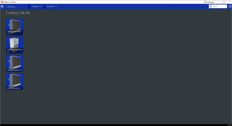
Cooling Coils
In this library, you can create several different chilled water coils. Below are the types of coils you can create:


Direct Evaporative
This coil consists of a rigid media evaporative pad, with water recirculated from a reservoir. The water is pumped from the reservoir to a water distribution header, for water feed by gravity from above the media. The evaporative pad provides the area for the adiabatic saturation of the air. While the process provides a lower dry-bulb temperature, the moisture content of the leaving air is higher than the entering condition. The direct stage is used for comfort cooling in a building where adding humidity to the air can be tolerated. This model can use a simple constant effectiveness or a variable effectiveness model that, under part load conditions, can modulate so that the air leaving the cooler just meets a drybulb temperature setpoint.


Product tab
Nominal Effectiveness
Default: 90%
Typical Range: 50 to 80%
Min/Max: 0 to 100%
Units: N/A
This field specifies the effectiveness at design flow rate that is applied to the wet bulb depression to determine the conditions leaving the cooler. This model assumes that the effectiveness can vary with supply air flow rate. For effectiveness variation with supply air flow fraction, enter into the curves tab to customize a curve.
 
Recirculating Pump
Full Load Energy Rate
Default: 30 W
Typical Range: 0 to 50 W
Min/Max: 0 to 999,999
Units: W, hp, kW, therms, W/(m3/sec), W/gpm, W/(L/sec)
This numeric input field is the recirculating and spray pump electric power for the water sprayed on the coil.
 
Evaporative Loss and Blowdown
Drift Loss
Default: 0%
Typical Range: 0 to 3%
Min/Max: 0 to 100
Units: %
This input field can be used to model additional water consumed by the cooler from drift. Drift is water that leaves the cooling media as droplets and does not evaporate into the process air stream. For example, water may get blown off the evaporative media by winds and escape the air system. The value entered here is a simple fraction of the water consumed by the cooler for normal process evaporation. The amount of drift is this fraction times the water evaporated for the normal cooling process.
 
Blowdown Concentration Ratio
Default: 3
Typical Range: 3 to 5
Min/Max: 3 to 5
Units: N/A
This input field can be used to model additional water consumed by the cooler from blowdown. Blowdown is water that is intentionally drained from the coolers sump to offset the buildup of solids in the water that would otherwise occur because of evaporation. It can be characterized as the ratio of solids in the blowdown water to solids in the make-up water and is dimensionless.
 
Operational Limits
Max Dry Bulb Limit
Default: None
Typical Range: High Limit and 82 to 100°F (High Limit and 28 to 35°C)
Min/Max: -999,999 to 999,999°F
Units: °F; °C
This input field defines the evaporative cooler air inlet dry bulb temperature maximum limits. The evaporative cooler will be turned off when the evaporative cooler air inlet node dry bulb temperature exceeds this value.
 
Min Dry Bulb Limit
Default: None
Typical Range: Low Limit and 60 to 70°F (High Limit and 28 to 35°C)
Min/Max: -999,999 to 999,999°F
Units: °F; °C
This input field defines the evaporative cooler inlet node dry bulb temperature minimum limit. The evaporative cooler will be turned off when evaporator cooler air inlet dry-bulb temperature falls below this value.
 
Max Wet Bulb Limit
Default: None
Typical Range: Low Limit and 75 to 82°F (High Limit and 24 to 28°C)
Min/Max: -999,999 to 999,999°F
Units: °F; °C
This input field defines the evaporative cooler air inlet node air wetbulb temperature maximum limits. When the evaporative cooler air inlet node air wetbulb temperature exceeds this limit, then the evaporative cooler is turns off.
 
 
Curve tab
Effectiveness Flow Ratio Modifier Curve
This curve modifies the effectiveness design value specified by multiplying the value by the result of this curve. The modifying curve is a function of flow fraction, which is the ratio of the current primary air flow rates divided by the design primary air flow rates. If this input curve is blank, the effectiveness is assumed to be constant. Any curve or table with one independent variable can be used.
 
Water Pump Power Modifier Curve
This curve modifies the pump electric power by multiplying the design power by the result of this curve. The normalized curve is a function of the primary air flow fraction as independent variable. The flow fraction is the ratio of the primary air during current operation divided by primary air Design Air Flow Rate. If this input field is left blank, the pump power is assumed to linear vary with the load.


Indirect Evaporative
This coil provides a model for a wetted coil evaporative cooler that has water sprayed directly on the tubes of the heat exchanger where latent cooling takes place. The vaporization of the water on the outside of the heat exchanger tubes allows the simultaneous heat and mass transfer which removes heat from the supply air on the tube side. Then the moist secondary air is exhausted. The secondary air stream has its own fan. This indirect evaporative coil can modulate so that the air leaving the cooler just meets a drybulb temperature setpoint. This coil is intended to be able to model indirect evaporative coils that have
1.      variable speed tower fans,
2.      variable speed pumps for water recirculation and spraying, and
3.      ability to operate in a dry mode.
Such indirect evaporative coils can modulate the cooling power during operation by varying either the tower fan speed or the intensity of water spray or both. To simplify the simulation it is assumed that the device’s internal controls are such that, when it is operating as a “Wet” evaporative cooler, tower fan and spray pump operation are linked together so that there is a one-to-one mapping between them at any given part load situation. This allows formulating the fan and pump power performance curves to be based on the same independent variable, tower air flow fraction.


Product tab
Design WB Effectiveness
Default: 90%
Typical Range: 50 to 80%
Min/Max: 0 to 100%
Units: N/A
This field specifies the design effectiveness that is applied to the wet bulb depression to determine the conditions leaving the cooler. This effectiveness is a complicated function of the efficiency with which heat and mass are transferred on the tower side and the efficiency of heat exchange between the tower and airside flows. The model assumes that the effectiveness a function of flow fraction. The flow fraction is the ratio of the sum of tower and airside current flow rates and the sum of the tower and airside design flow rates.
 
Enable DB Eff. Modifier
Default: No
Typical Range: N/A
Min/Max: N/A
Units: N/A
This field enables the design dry bulb effectiveness input to vary effectiveness of the evaporative cooler. It also enables the Drybulb Effectiveness Modifier Curve.
 
Design DB Effectiveness
Default: 90%
Typical Range: 50 to 80%
Min/Max: 0 to 100%
Units: N/A
This input is the nominal design dry bulb effectiveness with respect to dry bulb temperature difference, i.e., dry operation and at design air flow rates, and no water evaporation or spraying on the tower.
 
Recirculating Pump
Full Load Energy Rate
Default: 30 W
Typical Range: 0 to 50 W
Min/Max: 0 to 999,999
Units: W, hp, kW, therms, W/(m3/sec), W/gpm, W/(L/sec)
This numeric input field is the recirculating and spray pump electric power for the water sprayed on the coil.
 
Secondary Fan
Full Load Energy Rate
Default: Auto Size or 0.00022 kW/(cfm),  46.61W/(m3/sec)
Typical Range: 0 to 100
Min/Max: 0 to 999,999
Units: W/(cfm), W/(L/sec), W/(L/sec)-in H2O, kW/(cfm), kW/(L/sec), kW/(cfm)-in H2O, kW/(L/sec)-in H2O, W/(cfm)-in H2O, W/(m3/sec), BHP, W, kW
Enter the full load energy value and select the corresponding units to describe the amount of energy consumed by the secondary fan at design airflow.
 
Secondary Airflow Rate
Default: 100% Primary AIrflow
Typical Range: 50 to 100%
Min/Max: 0 to 100%
Units: % Primary Airflow
This field specifies the secondary airflow that will be flowing over the wetted heat exchanger tubes. This field is typically similar in magnitude to the primary airflow. This field can be autosized; if autosized, the program will determine if this loop is on the main air loop or an outdoor air path. If on the main air loop, the default value will be 100% of primary airflow. If on the outdoor air path, the flowrate is set to the larger of either the design minimum outdoor air intake or 50% of the main air loop design flow rate.
 
Evaporative Loss and Blowdown
Dewpoint Effectiveness
Default: 90%
Typical Range: 50 to 80%
Min/Max: 0 to 100%
Units: N/A
This field specifies an effectiveness that is applied to the dew point depression to determine a bound for the conditions leaving the cooler. The model uses the warmer of the two temperatures determined from wet bulb depression.
 
Blowdown Concentration Ratio
Default: 3
Typical Range: 3 to 5
Min/Max: 3 to 5
Units: N/A
This input field can be used to model additional water consumed by the cooler from blowdown. Blowdown is water that is intentionally drained from the coolers sump to offset the buildup of solids in the water that would otherwise occur because of evaporation. It can be characterized as the ratio of solids in the blowdown water to solids in the make-up water and is dimensionless.
 
Drift Loss
Default: 0%
Typical Range: 0 to 3%
Min/Max: 0 to 100
Units: %
This input field can be used to model additional water consumed by the cooler from drift. Drift is water that leaves the cooling media as droplets and does not evaporate into the process air stream. For example, water may get blown off the evaporative media by winds and escape the air system. The value entered here is a simple fraction of the water consumed by the cooler for normal process evaporation. The amount of drift is this fraction times the water evaporated for the normal cooling process.
 
Operational Limits
Min Dry Bulb Limit
Default: Low Limit
Typical Range: Low Limit and 60 to 70°F, (High Limit and 16 to- 21°C)
Min/Max: -999,999 to 999,999
Units: W/(cfm), W/(L/sec), W/(L/sec)-in H2O, kW/(cfm), kW/(L/sec), kW/(cfm)-in H2O, kW/(L/sec)-in H2O, W/(cfm)-in H2O, W/(m3/sec), BHP, W, kW
This input field defines the evaporative cooler inlet node dry bulb temperature minimum limit. The evaporative cooler will be turned off when evaporator cooler air inlet dry-bulb temperature falls below this value.
 
Operational Limits
Max Dry Bulb (DB) Limit
Default: None
Typical Range: High Limit and 82 to 100°F, High Limit and 28 to 35°C
Min/Max: -999,999 to 999,999
Units: °F; °C
This input field defines the evaporative cooler air inlet dry bulb temperature maximum limits. The evaporative cooler will be turned off when the evaporative cooler air inlet node dry bulb temperature exceeds this value. Typical ranges when high limit is used is between 82 - 100 F (or 28 – 35 C).
 
Max Wet Bulb Limit
Default: None
Typical Range: Low Limit and 75 to 82°F, High Limit and 24 to 28°C
Min/Max: -999,999 to 999,999
Units: °F; °C
This input field defines the evaporative cooler air inlet node air wetbulb temperature maximum limits. When the evaporative cooler air inlet node air wetbulb temperature exceeds this limit, then the evaporative cooler is turns off. Typical ranges when high limit is used is between 75 - 82 F (or 24 – 28 C).
 
 
Curve tab
Drybulb Effectiveness Modifier Curve
This curve modifies the drybulb effectiveness by multiplying the design effectiveness value by the result of this curve. The curve is evaluated low fraction as independent variable. The flow fraction is the ratio of sum of the primary and secondary flow rates divided by the sum of the design flow rates. If this input field is left blank, the effectiveness is assumed to be constant.
 
Wetbulb Effectiveness Modifier Curve
This curve modifies the wetbulb effectiveness by multiplying the design effectiveness value by the result of this curve. The curve is evaluated low fraction as independent variable. The flow fraction is the ratio of sum of the primary and secondary flow rates divided by the sum of the design flow rates. If this input field is left blank, the effectiveness is assumed to be constant.
 
Fan Power Curve
The normalized curve modifies the design secondary air fan power in the previous field by multiplying the value by the result of this curve. The normalized curve is a function of the secondary side flow fraction as independent variable. The flow fraction is the secondary air flow rate during operation divided by Secondary Design Air Flow Rate. If this input field is left blank, the fan power is assumed to be constant.
 
Pump Power Curve
This curve modifies the pump electric power in the previous field by multiplying the design power by the result of this curve. The normalized curve is a function of the secondary side flow fraction as independent variable. The flow fraction is the secondary air flow rate during operation divided by Secondary Design Air Flow Rate.


Water (Detailed)
 
 
Number of Rows
Default: 4
Typical Range: 2 to 6
Min/Max: 1 to 100
Units: N/A
This input is the number of tube rows in the direction of the airflow.
 
Minimum Face Area
Default: Autosized
Typical Range: 1 to 75 sq ft (0.1 to 7 sq m)
Min/Max: 0 to 999,999 (IP and SI)
Units: sq ft, sq in, sq mm, sq m, sq cm
The minimum cross sectional area available for air passage.
 
Coil Height
Default: Autosized
Typical Range: 12 to 60" (30.5 to 152.4 cm)
Min/Max: 0 to 999,999 (IP and SI)
Units: ft, in, cm, mm, m
The height of the cooling coil.
 
Coil Depth
Default: Autosized
Typical Range: 12 to 60" (30.5 to 152.4 cm)
Min/Max: 0 to 999,999 (IP and SI)
Units: ft, in, cm, mm, m
The distance from the front of the coil to the back of the coil in the airflow direction. Also called the fin depth.
 
Fin
Surface Area
Default: Autosized
Typical Range: N/A
Min/Max: 0 to 999,999 (IP and SI)
Units: sq ft, sq in, sq cm, sq mm, sq m
The total surface area of fins attached to the coil.
 
Thickness
Default: .007in (.178 mm)
Typical Range: 0.45 to .08 in
Min/Max: 0 to 999,999 (IP and SI)
Units: ft, in, cm, mm, m
Thickness of the airside fins.
 
Spacing
Default: .07 in (2.225 mm)
Typical Range: .06 to .08 in
Min/Max: 0 to 999,999 (IP and SI)
Units: ft, in, cm, mm, m
The spacing of the fins, centerline to centerline.
 
Thermal Conductivity
Default: 117.85 Btu/(hrftF); (204 W/mK)
Typical Range: N/A
Min/Max: 0 to 999,999 (IP and SI)
Units: Btu/(hrftF), W/mK, W/mC
The thermal conductivity of the fin material.
Input Consideration: Default fin thermal conductivity is aluminum at 68 degrees F.
 
Tube
Inside Diameter
Default: 0.57 in; (14.478 mm)
Typical Range: 0.57 to 0.7 in
Min/Max: 0 to 999,999 (IP and SI)
Units: ft, in, cm, mm, m
The inside diameter of the tubes.
 
Outside Diameter
Default: 0.63 in; (16.002 mm)
Typical Range: 0.63 to 0.75 in
Min/Max: 0 to 999,999 (IP and SI)
Units: ft, in, cm, mm, m
The outside diameter of the tubes.
 
Inside Surface Area
Default: Autosized
Typical Range: N/A
Min/Max: 0 to 999,999 (IP and SI)
Units: sq ft, sq in, sq cm, sq mm, sq m
The total surface area inside the tubes (water side).
 
Depth Spacing
Default: 1.02 in; (25.908 mm)
Typical Range: 0.87 to 1.5 in
Min/Max: 0 to 999,999 (IP and SI)
Units: ft, in, cm, mm, m
The outside diameter of the tubes.
Input Consideration:
5/8” tubes = 1.5” row spacing
1/2” tubes = 1.0825” row spacing
3/8” tubes = 0.87” row spacing
 
Exposed Surface Area
Default: Autosized
Typical Range: N/A
Min/Max: 0 to 999,999 (IP and SI)
Units: sq ft, sq in, sq cm, sq mm, sq m
The total surface area outside the tubes (i.e. the outside area of the unfinned tubes minus the area of tubes covered by the fins).
 
Number of Tubes per Row
Default: Autosized
Typical Range: N/A
Min/Max: 0 to 999,999 (IP and SI)
Units: N/A
The number of tubes per row.
 
Thermal Conductivity
Default: 222.99 btu/(hrftF); (386 W/(mC))
Typical Range: N/A
Min/Max: 0 to 999,999 (IP and SI)
Units: btu/(hrftF); W/(mC); W/(mK)
The thermal conductivity of the tube material.
Input Consideration: Default tube thermal conductivity is copper at 68 degrees F.
 
 
Water (Simple)
The water cooling coil has the ability to give detailed output with simplified inputs, inputting complicated coil geometry is not required by the user for this model instead the coil is sized in terms of auto-sizeable thermodynamic inputs. The coil requires thermodynamic inputs such as temperatures, mass flow rates and humidity ratios which come from the build, system, and location you have entered into your project.
The coil is sized using auto-sized input conditions and the UA values are calculated from the design conditions. A rough estimate of the coil area is provided along with percentage of surface wet and/or dry.
The basic underlying idea is - use auto sizable thermodynamic design inputs, calculate the coil UAs, use these UA values and operating conditions, calculate the outlet stream conditions, and calculate the heat transfer rates.


Heat Exchanger Type
Default: Counterflow
Typical Range: N/A
Min/Max: N/A
Units: N/A
The coil is operable in two modes, Cross Flow for general A/C applications and Counter flow mode. Air-conditioning systems generally use cross flow heat exchangers, hence the default is set to cross flow.
 
Calculation Mode
Default: Simple Condensation
Typical Range: N/A
Min/Max: N/A
Units: N/A
The coil has two modes of operation, termed as Simple and Detailed. The difference between the two modes being, the simple mode reports the value of surface area fraction wet of the coil as dry or wet. The detailed mode give the exact value, however the execution time in detailed mode is noticeably higher.