Trace 3D Plus
User Guide
 
×


Fans
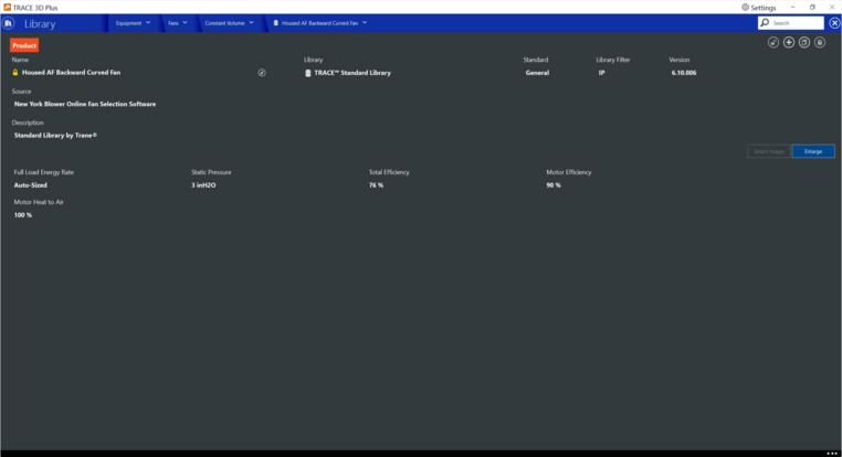
In the fans section of the equipment library, fan library members can be viewed, modified, or created for use in a TRACE™ 3D Plus project file. There are two types of Fans in this library; Constant Volume and Variable Volume. The selectable field options are similar in both Constant and Variable Fan sections. All available fan options will have a Product tab on the detailed library input screen.
Note: Standard TRACE library members cannot be modified or deleted but can be copied and used as the starting point for a user made custom library member. 


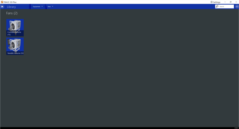
Constant and Variable Volume


Product tab
 
Full Load Energy Rate
Default: Auto Size
Typical Range: 0 to 999,999,999,999,999.9999999
Min Max: N/A
Units: W; kW; W/(m3/sec); W/((m3/sec)·Pa); W/(cfm); W/(L/sec); W/((L/sec)·Pa); kW/(cfm); kW/(L/sec); kW/(cfm·in H2O); kW/((L/sec)·Pa); W/(cfm·inH2O); bhp
Enter the full load energy value and select the corresponding units to describe the amount of energy consumed by the fan at design airflow. For example, if a fan consumes .000321 kW per CFM per inch of static pressure, enter .000321 as the value and select kW/CFM-in wg as the units.
 
The default is the Auto Size checkbox checked. This will have the program auto-size the fan using static pressure, total efficiency and motor efficiency inputs. To manually set the full load energy rate, deselect this box.
 
Static Pressure
Default: 3 in H2O [IP], 746.52 Pa [SI]
Typical Range: 0 to 999,999,999,999,999.9999999
Min Max: N/A
Units: Not selectable, inches H20 for IP or Pa for SI
Enter the fan total static pressure in either inches H20 or Pa. This value is used to calculate the full load energy rate of the fan if Auto Size is checked or the energy rate has static pressure in the units.
 
Total Efficiency
Default: 70
Typical Range: 0 to 100
Min Max: N/A
Units: %
This value is the overall efficiency of the fan, i.e., the ratio of the power delivered to the fluid to the electrical input power. It is the product of the motor efficiency and the impeller efficiency. The motor efficiency is the power delivered to the shaft divided by the electrical power input to the motor. The impeller efficiency is power delivered to the fluid (air) divided by the shaft power. The power delivered to the fluid is the mass flow rate of the air multiplied by the pressure rise divided by the air density. This input value must be between 0 and 100.
 
 
Motor Efficiency
Default: 90
Typical Range: 0 to 100
Min Max: N/A
Units: %
This value is the shaft power divided by the electrical power consumed. This input value must be between 0 and 100.
 
 
Schedule
Default: Available (100%)
Typical Range: N/A
Min Max: N/A
Units: N/A
The name of the schedule that denotes whether the fan can run during a given time period. A schedule value of 0 indicates that the fan is off for that time period. A schedule value greater than 0 indicates that the fan can operate during the time period. If this field is blank, the schedule has values of 1 for all time periods. Applicable availability managers may override this schedule by forcing the fan to be on or off.
 
 
Motor Heat to Air
Default: 100%
Typical Range: 0 to 100
Min Max: N/A
Units: %
This value is the fraction of the motor heat that is added to the air stream. A value of 0 means that the motor is completely outside the air stream.  A value of 100 means that all of the motor heat loss will go into the air stream and act to cause a temperature rise. This value must be between 0 and 100.
 
 
Curve tab
Select this tab to enter part load and unloading curve information for variable volume fans. 
 
Note: This button is only available for variable volume fans. 
 
See the Reference page for resources used in the help documentation.