Trace 3D Plus
User Guide
 
×


Generators
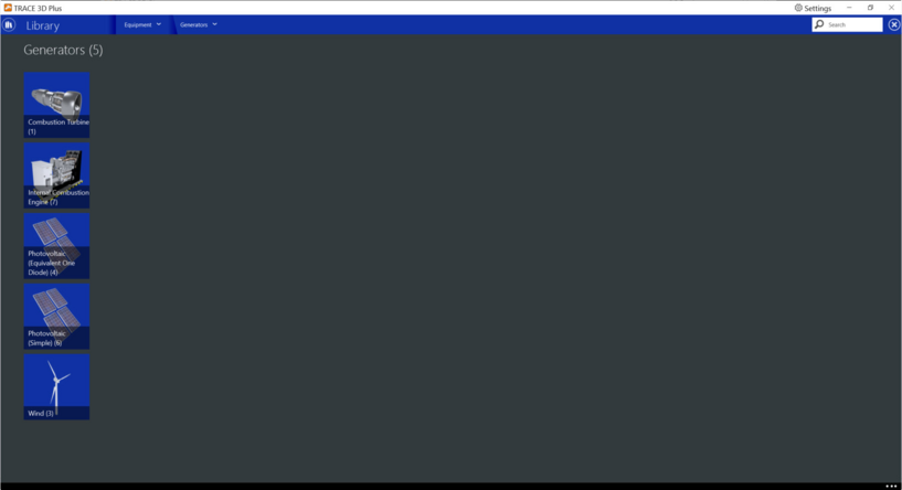
In the generators section of the equipment library, power generation library members can be viewed, modified, or created for use in a TRACE™ 3D Plus project file. There are five types of generator categories in this library; Combustion Turbine, Internal Combustion Engine, Photovoltaic (Equivalent One Diode), Photovoltaic (Simple), and Wind.
 
 
Note: Standard TRACE library members cannot be modified or deleted but they can be copied and edited. 


Combustion Turbine
Combustion Turbines are pieces of equipment that burn a fuel source to spin a turbine that generates electricity. TRACE™ 3D Plus utilizes a Brayton Cycle model that originated from a computer program called BLAST. The Brayton Cycle or “open cycle” consists of adiabatic compression, constant pressure heating, and adiabatic expansion. This model uses electrical load and engine generator size to compute part load ratios (PLR). Fuel energy input, recoverable lube oil heat, and recoverable exhaust heat are then computed. 
Combustion turbine generators use performance parameters to compute fuel energy consumption as a function of part-load and ambient (entering) air temperature. Recoverable fuel energy equipment, recoverable lube oil heat/fuel energy input equipment performance, total exhaust heat/fuel energy input equipment, exhaust gas temperature/fuel energy input equipment performance parameters are all specified with a quadratic curve fit. 
When the heat recovery curve fits = 0.0, this means that no heat recovery is done on the diesel generator exhaust gas; and no heat recovery is specified. 
 
 
Curve tab
 
 
Product tab
The product tab contains all of the design parameters that define the combustion turbine generator. To define the part load conditions using unloading curves, click the curves tab of the combustion turbine library. The curves that are available for combustion turbines are; fuel use, fuel input, fuel input temperature, exhaust flow, and temperature based exhaust temperature. 
 
Rated Full Load Power
Default Value: 102,364 Btuh [IP], 30,000 W [SI]
Typical Range: -999 x1012 to 999 x1012
Min & Max: N/A
Units: Btuh, kW, W
Enter the design nominal capacity of the combustion turbine generator. 
 
Optimum Part Load Ratio
Default Value: 100%
Typical Range: 0 to 100
Min & Max: N/A
Units: %
This field contains the optimal fraction of full load, meaning this is the part load ratio that gives the optimal production of electricity with the least amount of fuel usage. 
 
Fuel Type
Default Value: Natural Gas
Typical Range: N/A
Min & Max: N/A
Units: Diesel, Gasoline, Natural Gas, Coal, Propane Gas, Fuel Oil #1, Fuel Oil #2
This field determines which fuel is consumed by the generator. 
  
Fuel Higher Heating Value
Default Value: 43,500 kJ/kg
Typical Range: -999 x1012 to 999 x1012
Min & Max: N/A
Units: Btu/lb, J/kg, kJ/kg
This numeric field contains the higher heating value (or gross energy) of the fuel used by the generator. 
 
Design Air Inlet Temperature
Default Value: 77 °F [IP], 25 °C [SI]
Typical Range: -999 x1012 to 999 x1012
Min & Max: N/A
Units: °F, °C
Enter the design entering air temperature going into the generator. 
 
Heat Recovery
Enable Heat Recovery
Default Value: No
Typical Range: No, Yes
Min & Max: N/A
Units: N/A
This toggle allows you to turn on or off heat recovery. If yes is selected, applicable energy recovery inputs will appear. 
 
Design Heat Recovery Water Flow Rate
Default Value: 0 gmp [IP], 0 m3/s [SI]
Typical Range: -999 x1012 to 999 x1012
Min & Max: N/A
Units: gpm, L/s, m3/hr, m3/s, Autosize
Enter the design water volumetric flow rate through the heat recovery loop. 
 
Heat Recovery Maximum Temperature
Default Value: 176°F [IP], 80°C [SI]
Typical Range: -999 x1012 to 999 x1012
Min & Max: N/A
Units: °F, °C
This field sets the maximum temperature that this piece of equipment can produce for heat recovery. The idea behind this field is that the current models do not take temperatures into account for availability and they just pass heat around the loop without a temperature limit. This temperature limit puts an upper bound on the recovered heat and limits the max temperatures leaving the component.
As temperatures in the loop approach the maximum temperature, the temperature difference between the entering water and the surfaces in the piece of equipment becomes smaller. For the given heat recovery flow rate and that temperature difference the amount of heat recovered will be reduced, and eventually there will be no heat recovered when the entering water temperature is equal to the maximum temperature specified by the user in this field. The reduced amount of heat recovered will diminish if the temperature of the loop approach is the maximum temperature, and this will show up in the reporting. This allows the user to set the availability or the quality of the heat recovered for usage in other parts of the system or to heat domestic hot water supply.
 
Heat Recovery Pump
Default Value: CV Chilled Water Pump
Typical Range: N/A
Min & Max: N/A
Units: N/A
Choose which pump will be used for your heat recovery pump from the available Pumps Library.   
 
Heat Recovery Pump Type
Default Value: Constant Speed Pump
Typical Range: N/A
Min & Max: N/A
Units: N/A
Choose which type of pump will be used for the heat recovery pump.  Choose either constant or variable volume.   
 
Exhaust Flow
Design Minimum Exhaust Temperature
Default Value: 302°F [IP], 150 °C [SI]
Typical Range: -999 x1012 to 999 x1012
Min & Max: N/A
Units: °F, °C
This is the design stack saturated steam temperature of the generator and the minimum temperature the exhaust can be. 
 
Exhaust Flow per Engine Capacity
Default Value: 0.00000063 (kg/s)/W
Typical Range: -999 x1012 to 999 x1012
Min & Max: N/A
Units: (kg/s)/W, (kg/hr)/W, (lb/hr)/W
Enter the maximum exhaust flow per unit capacity for combustion generators. This parameter sets an upper limit on exhaust gas flow and exhaust gas heat recovery for generators.
 
*See the Reference page for resources used in the help documentation.


Internal Combustion Engine
Internal combustion engines are pieces of equipment that burn a fuel source to generate electricity. TRACE™ 3D Plus utilizes a modified Otto Cycle model. This generator model uses the electrical load and rated engine generator size to compute part-load ratios (PLR). Fuel energy input and recoverable jacket and lube oil heat are then computed. Finally, the recoverable exhaust heat is calculated. 
Manufacturer's curves or tables must be obtained for IC engine generators to derive the equipment performance parameters that are specified in the quadratic curve fits. Note that simple transformation of the form of the manufacturer's curves may be required. Electric energy output/fuel energy input is related to the part-load ratio (i.e., electric/load generator capacity) with a polynomial. Recoverable jacket heat/fuel energy equipment, recoverable lube oil heat/fuel energy input equipment performance, total exhaust heat/fuel energy input equipment, exhaust gas temperature/fuel energy input equipment performance parameters are all specified with a quadratic curve fit.
When the heat recovery curve fits = 0.0, this means that no heat recovery is done on the IC engine generator exhaust gas; and no heat recovery is specified.


Product tab
The product tab contains all of the design parameters that define the internal combustion engine.   


Rated Full Load Power
Default Value: 170,607 Btuh [IP], 50000 W [SI]
Typical Range: -999 x1012 to 999 x1012
Min & Max: N/A
Units: Btuh, kW, W
Enter the design nominal capacity of the combustion turbine generator. 
 
 
Optimum Part Load Ratio
Default Value: 100%
Typical Range:0 to 100
Min & Max: N/A
Units: %
This field contains the optimal fraction of full load, meaning this is the part load ratio that gives the optimal production of electricity with the least amount of fuel usage. 
 
Fuel Type
Default Value: Electricity
Typical Range: -999 x1012 to 999 x1012
Min & Max: N/A
Units: Diesel, Gasoline, Natural Gas, Coal, Propane Gas, Fuel Oil #1, Fuel Oil #2
This field determines which fuel is consumed by the generator.   
 
Fuel Higher Heating Value
Default Value: 43,500 kJ/kg
Typical Range: -999 x1012 to 999 x1012
Min & Max: N/A
Units: Btu/lb, J/kg, kJ/kg
This numeric field contains the higher heating value (or gross energy) of the fuel used by the generator. 
 
Heat Recovery
Enable Heat Recovery
Default Value: No
Typical Range: N/A
Min & Max: N/A
Units: No, Yes
This toggle allows you to turn on or off heat recovery. If yes is selected, applicable energy recovery inputs will appear. 
 
Design Heat Recovery Water Flow Rate
Default Value: 0 gmp, 0 m3/s
Typical Range: -999 x1012 to 999 x1012
Min & Max: N/A
Units: gpm, L/s, m3/hr, m3/s, Autosize
Enter the design water volumetric flow rate through the heat recovery loop. 
 
Heat Recovery Maximum Temperature
Default Value: 176°F [IP], 80°C [SI]
Typical Range: -999 x1012 to 999 x1012
Min & Max: N/A
Units: °F, °C
This field sets the maximum temperature that this piece of equipment can produce for heat recovery. The idea behind this field is that the current models do not take temperatures into account for availability and they just pass heat around the loop without a temperature limit. This temperature limit puts an upper bound on the recovered heat and limits the max temperatures leaving the component.
As temperatures in the loop approach the maximum temperature, the temperature difference between the entering water and the surfaces in the piece of equipment becomes smaller. For the given heat recovery flow rate and that temperature difference the amount of heat recovered will be reduced, and eventually there will be no heat recovered when the entering water temperature is equal to the maximum temperature specified by the user in this field. The reduced amount of heat recovered will diminish if the temperature of the loop approach is the maximum temperature, and this will show up in the reporting. This allows the user to set the availability or the quality of the heat recovered for usage in other parts of the system or to heat domestic hot water supply.
 
Heat Recovery Pump Type
Default Value: Constant Speed Pump
Typical Range: N/A
Min & Max: N/A
Units: N/A
Choose which pump will be used for your heat recovery pump from the available Pumps Library.   
 
Heat Recovery Pump
Default Value: C90.1 CV Chilled Water Pump
Typical Range: N/A
Min & Max: N/A
Units: N/A
Choose which type of pump will be used for the heat recovery pump. Choose either constant or variable volume.   
 
Exhaust Flow
Design Minimum Exhaust Temperature
Default Value: 302°F [IP], 150°C [SI]
Typical Range: -999 x1012 to 999 x1012
Min & Max: N/A
Units: °F, °C
This is the design stack saturated steam temperature of the generator and the minimum temperature the exhaust can be. 
 
Exhaust Flow per Engine Capacity
Default Value: 0.00000063 (kg/s)/W
Typical Range: -999 x1012 to 999 x1012
Min & Max: N/A
Units: (kg/s)/W, (kg/hr)/W, (lb/hr)/W
Enter the maximum exhaust flow per unit capacity for combustion generators. This parameter sets an upper limit on exhaust gas flow and exhaust gas heat recovery for generators.
 
*See the Reference page for resources used in the help documentation.
 
 
Curve tab
To define the part load conditions using unloading curves, click the curves tab of the combustion turbine library. Exhaust Temperature Curve, Total Exhaust Energy Curve, and Shaft Power Curve are all available curves that can be defined on the curves tab. 


Photovoltaic (Equivalent One Diode)
Photovoltaic generators, also known as solar panels, collect the suns energy and convert it into electricity.
This model describes the performance characteristics of Photovoltaic (PV) modules to be modeled using an equivalent one-diode circuit. This model is also known at the 4- or 5-parameter TRNSYS model for photovoltaics. The Photovoltaic information found in the Energy Plus Input Output Reference Manual shows several sample PV array types with their input values. The fields for this library member can be found below.   


Cell Type
Default Value: Crystalline Silicon
Typical Range: N/A
Min & Max: N/A
Units: Crystalline Silicon, Amorphous Silicon
This field is used to describe the type of technology used in the PV module. There are two options available, Crystalline Silicon and Amorphous Silicon. The choice affects the methodology used to calculate electricity generation. 
 
Number of Cells in Series
Default Value: 1
Typical Range: 1 to 999 x 1012
Min & Max: N/A
Units: Integer
This field is an integer representing the number of individual cells wired in series to make up a single module. The typical number for a 12V crystalline silicon PV module is 36. 
 
Active Area
Default Value: 108 ft2 [IP], 0.63 m2 [SI]
Typical Range: 1 to 999 x 1012
Min & Max: N/A
Units: ft2, cm2, in2, m2, mm2
This field is the total active area of the PV module. 
 
Absorptance Transmittance
Default Value: 0.9
Typical Range: -999 x 1012 to 999 x 1012
Min & Max: N/A
Units: N/A
This field indicates the transmittance-absorptance product at normal incidence angles for the PV modules. If the transmittance-absorptance product is positive, that value will be used for all angles of incidence. If the value specified is negative, then the magnitude of the given value will be used for normal incidence and the IAM modifier correlation will be used for all other angles.
 
Semiconductor Bandgap
Default Value: 1.12 eV
Typical Range: 1 to 999 x 1012
Min & Max: N/A
Units: eV (electron volts)
This field is the semiconductor bandgap for the PV material. The bandgap for silicon is 1.12 eV. 
 
PV Electrical Characteristics
Shunt Resistance
Default Value: 1,000,000 ohms
Typical Range: 0 to 999 x 1012
Min & Max: N/A
Units: ohms
This field is the shunt (parallel resistance in the single diode electrical model of the PV. The shunt resistance is effectively infinite for crystalline silicon based PV modules and is finite for thin film and exotic metal modules. 
 
Short Circuit Current
Default Value: 4.75 Amps
Typical Range: 0 to 999 x 1012
Min & Max: N/A
Units: Amps
This field is the short circuit current (in Amps) for an individual module in the PV array at reference conditions. 
 
Open Circuit Voltage
Default Value: 21.4 Volts
Typical Range: 0 to 999 x 1012
Min & Max: N/A
Units: Volts
This field is the open circuit voltage (in volts) for an individual module in the PV array at reference conditions. 
 
Reference Temperature
Default Value: 77F [IP], 25°C [SI]
Typical Range: 0 to 999 x 1012
Min & Max: N/A
Units: °F, °C [SI]
This field is the ambient temperature (in °F) at reference conditions. 
 
Reference Radiation Level
Default Value: 1000 W/m2
Typical Range: 0 to 999 x 1012
Min & Max: N/A
Units: W/m2
This field is the radiation level (in W/m2) at reference conditions. Also known as Reference Insolation. 
 
Module Current at Maximum Power
Default Value: 4.45 Amps
Typical Range: 0 to 999 x 1012
Min & Max: N/A
Units: Amps
This input is module current at the maximum power point and reference conditions. 
 
Module Voltage at Maximum Power
Default Value: 17 Volts
Typical Range: 0 to 999 x 1012
Min & Max: N/A
Units: Volts
This input is module voltage at the maximum power point and reference conditions. 
 
 
Cell Temperature
Cell Ambient Temperature
Default Value: 68°F [IP], 20°C [SI]
Typical Range: 0 to 999 x 1012
Min & Max: N/A
Units: °F, °C [SI]
This input represents the ambient temperature from the nominal operating cell temperature (NOCT) test. 
 
Cell Test Cell Temperature
Default Value: 117°F [IP], 47°C [SI]
Typical Range: 0 to 999 x 1012
Min & Max: N/A
Units: °F, °C [SI]
This input represents the cell temperature from the nominal operating cell temperature (NOCT) test. 
 
Cell Test Insolation
Default Value: 800 W/m2
Typical Range: 0 to 999 x 1012
Min & Max: N/A
Units: W/m2
This input represents the insolation level from the nominal operating cell temperature (NOCT) test. 
 
Temperature Coefficients
Short Circuit Current Coefficient
Default Value: 0.00065 A/°K
Typical Range: 0 to 999 x 1012
Min & Max: N/A
Units: A/°K
This field accounts for the fact that the module short circuit current is temperature dependent. The coefficient is given in Amps/Kelvin. 
 
Open Circuit Voltage Coefficient
Default Value: - 0.08 V/°K
Typical Range: -999 x 1012 to 999 x 1012
Min & Max: N/A
Units: V/°K
This field accounts for the fact that the module open circuit voltage is temperature dependent. The coefficient is given in Volts/Kelvin. 
 
*See the Reference page for resources used in the help documentation.
 
 
Photovoltaic (Simple)
This solar panel library describes a simple model of photovoltaics that may be useful for early phase design analysis. In this model the user has direct access to the efficiency with which surfaces convert incident solar radiation to electricity and need not specify arrays of specific modules. The full geometric model for solar radiation is used, including shading and reflections, to determine the incident solar resource. This model is intended to be useful for design purposes to quickly get an idea of the levels for annual production and peak power. The model can also accept arbitrary conversion efficiencies and does not require actual production units be tested to obtain performance coefficients. 


Cell Efficiency
Default Value: 12% [IP] [SI]
Typical Range: 0 to 100
Min & Max: N/A
Units: %
This field specifies the efficiency with which solar incident energy is converted to electricity. Efficiency = (electrical power generated [W])/(power of incident solar[W]). The efficiency value is dimensionless and should be between 0 and 100%
 
*See the Reference page for resources used in the help documentation.
 
 
Wind
A wind turbine is a component that converts the kinetic energy of the surrounding airstream into electricity. This model is intended to calculate the electrical power that a wind turbine system produces. The performance of wind turbine systems is dependent on the local environmental conditions such as wind speed and density of air at the height of the systems. An analysis of these conditions is necessary to accurately estimate power output.
The model employs the general kinetic energy equation to calculate the performance characteristics of the horizontal axis wind turbine (HAWT) system. It provides a simple approximation algorithm when the power coefficient, Cp, is available which represents the efficiency of the wind turbine in the wind power extraction from the ambient air stream. It also allows the user to input experimental constants so that the power coefficient can precisely be determined according to the characteristic of the airfoil of the system. As for the vertical axis wind turbine (VAWT) systems, it employs the general mathematical equations for straight-bladed Darrieus-type VAWT systems, which are common to VAWT systems. Various types of VAWT systems such as the Savonius-type and the curved-blade (or Egg-beater) type may be simulated with this same model.
This library includes two different types of dynamic power control: Fixed Speed Fixed Pitch (FSFP) and Variable Speed Fixed Pitch (VSFP). Currently, it does not include an algorithm for modeling pitch control such as Fixed Speed Variable Pitch (FSVP) and Variable Speed Variable Pitch (VSVP). If the control type of the wind turbine is either FSVP or VSVP, the control type of VSFP will be assumed. In addition, constant power generation is assumed when the ambient wind speed is between the rated wind speed and the cut out wind speed, if the user specifies one of the last three options. The model also has the ability to account for transient losses associated with the power produced during dynamic control by a user-specified fraction.
The model does not include detailed algorithms for generators and inverters due to concerns for computational convergence, time, and usability. Instead, all conversion losses of these subsystems are included by applying a user-supplied total system efficiency to the maximum power extraction of the wind turbine. The field of the total system efficiency must be specified by the user.


Power Control
Default Value: Variable Speed Fixed Pitch
Typical Range: N/A
Min & Max: N/A
Units: Variable Speed Fixed Pitch, Fixed Speed Fixed Pitch
This input is the type of rotor control for the wind turbine.  This protects the system against the overloading for a system with no speed or pitch control and also to maximize the energy yield for the system. 
Four different control types are classified in the literature: Fixed Speed Fixed Pitch (FSFP), Fixed Speed Variable Pitch (FSVP), Variable Speed Fixed Pitch (VSFP), and Variable Speed Variable Pitch (VSVP). Currently, FSFP and VSFP types can be modeled in TRACE™ 3D Plus and Energy Plus. The other two types will be modeled as VSFP. If the first FSFP control type is chosen, the model assumes the maximum power at a fixed rotor speed when the power output predicted is greater than the maximum until the rotor speed reaches the maximum wind speed.  If one of the last three control options is chosen, the model assumes that the system produces a constant power at the rated wind speed when the wind speed is between the rated wind speed and cut-out wind speed. The default value is Variable Speed Fixed Pitch (VSFP).
 
Rated Full Load Power
Default Value: 10,000 W
Typical Range: 0 to 999 x 1012
Min & Max: N/A
Units: HP, kW, W
Enter the nominal power output of the wind turbine system at the rated wind speed in Watts. Note that the user should input the maximum power of the system with no control, i.e., FSFP control type, can physically produce. Manufacturer’s data also indicates it as peak power or rated capacity. If the local wind speed is greater than the rated wind speed, the model assumes constant power output of this field.
 
System Efficiency
Default Value: 75%
Typical Range: 1 to 100
Min & Max: N/A
Units: %
Enter the overall system efficiency of the wind turbine system. It includes all the conversion losses as well as transient losses during the dynamic control when the ambient wind speed is between the rated wind speed and cut-out wind speed. The user also has the ability to specify delivery losses from the system to the local area such as transmission and inverter inefficiencies.
 
Total Height
Default Value: 36 ft [IP], 11 m [SI]
Typical Range: 0 to 999 x 1012
Min & Max: N/A
Units: cm, ft, in, m, mm
This field is the height of the hub of the HAWT system, or of the pole of the VAWT system. It is necessary to estimate local air density and the wind speed at this particular height where the wind turbine system is installed.
 
Maximum Tip Speed Ratio
Default Value: 5
Typical Range: 0 to 12
Min & Max: N/A
Units: Dimensionless Ratio
This field is the maximum tip speed ratio between the rotor velocity and ambient wind velocity. The rotor speed varies with this ratio to maximize the power output when the rotor control types are variable speed. This field allows the user to adjust the power output from the particular system or to find the optimal tip speed ratio of the system. Optimal tip speed ratio is dependent on the number of blades. This ratio is typically about 6, 5, and 3 for two-bladed, three-bladed, and four-bladed rotor, respectively. For the vertical axis wind turbine, it is smaller than horizontal axis wind turbine, and varies with the chord area. The default and maximum values are 5.0 and 12.0 respectively.
 
Maximum Power Coefficient
Default Value: 0.5
Typical Range: 0 to 0.59
Min & Max: N/A
Units: Dimensionless
This field is the maximum fraction of power extraction from ambient wind. If the user inputs this field, the simple approximation model is assumed. The model simply employs the value of this field into the general kinetic energy equation, so that the power output is obtained. The user can obtain this field with a simple calculation from the power curve published in almost all manufacturers' specifications by using the kinetic energy equation as:
 
 
Where
P = power production at the rated wind speed [W]
ρ = density of air [kg/m3]
A = swept area of rotor [m2]
V = rated wind speed [m/s]
Cp = power coefficient
The maximum and default values are 0.59 and 0.35.
 
Rotor - Blade Characteristics
Number of Blades
Default Value: 3
Typical Range: 1 to 100
Min & Max: N/A
Units: Integer
Enter the number of blades of the wind turbine. The azimuth angle of the rotor of the VAWT system is determined by dividing 360 degree by this field so that the model determines the chordal velocity component and the normal velocity component of the system. The default number of blades is 3.
 
Rotor Type
Default Value: Horizontal
Typical Range: N/A
Min & Max: N/A
Units: Dimensionless
Enter the type of axis of the wind turbine. The user specifies either a horizontal axis wind turbine or a vertical axis wind turbine. Each type of wind turbine employs a different algorithm for the calculation of the electrical power output of the wind turbine. The default value is Horizontal Axis Wind Turbine.
 
Rated Rotor Speed
Default Value: 130 RPM [IP], [SI]
Typical Range: 0 to 999 x 1012
Min & Max: N/A
Units: rad/s, rpm, rps
Enter the maximum rotational speed of the rotor at the rated power of the wind turbine. It is used to determine the tip speed ratio of the rotor and relative flow velocity incident on a single blade of the VAWT systems.
 
Rotor Diameter
Default Value: 17 ft [IP], 5.2 m [SI]
Typical Range: 0 to 999 x 1012
Min & Max: N/A
Units: cm, ft, in, m, mm
Enter the diameter of the rotor in meters. Note that this field is not the height of the blade, but the diameter of the perpendicular circle from the vertical pole in the VAWT systems. It determines the swept area of the rotor of the HAWT systems and the chordal velocity of the VAWT systems.
 
Blade Chord Area
Default Value: 22 ft2 [IP], 2.08 m2 [SI]
Typical Range: 0 to 999 x 1012
Min & Max: N/A
Units: cm2, ft2, in2, m2, mm2
Input the blade chord area of a single blade of VAWT system. This value is necessary to determine the net tangential and normal forces of a single blade.
 
Blade Drag Coefficient
Default Value: 0.9
Typical Range: 0 to 999 x 1012
Min & Max: N/A
Units: Dimensionless
This field is the blade drag coefficient for a specific blade. It is for determining the tangential and normal force coefficients with the blade lift coefficient (see next field) so that the model can calculate the power output from the system. The user should be able to obtain this parameter for a specific blade from the manufacturer’s data. This field is only valid for VAWT systems.
 
Blade Lift Coefficient
Default Value: 0.05
Typical Range: 0 to 999 x 1012
Min & Max: N/A
Units: Dimensionless
This field is the blade lift coefficient for a specific blade. It is for determining the tangential and normal force coefficients with the blade drag coefficient (see previous field) so that the model can calculate the power output from the system. The user should also be able to obtain it for a specific blade from the manufacturer’s data. This field is only valid for VAWT systems.
 
Wind Speed
Rated Wind Speed
Default Value: 2165 ft/min [IP], 11 m/s [SI]
Typical Range: 0 to 999 x 1012
Min & Max: N/A
Units: cm/s, ft/min, ft/s, km/hr, m/min, m/s, mi/min, mph
Enter the wind speed that the wind turbine system indicates the peak in the power curve. The system produces the maximum power at this speed and the speed of the rotor is managed based on this wind speed.
 
Cut in Wind Speed
Default: 591 ft/min [IP], 3 m/s [SI]
Range: 0 - 999x1012
Units: cm/s, ft/min, ft/s, km/hr, m/min, m/s, mi/min, mph
 
Enter the lowest wind speed where the wind turbine system can be operated. No power generation is achieved as long as the ambient wind speed is lower than this speed.
 
Cut out Wind Speed
Default Value: 4,912 ft/min [IP], 25 m/s [SI]
Typical Range: 0 to 999 x 1012
Min & Max: N/A
Units: cm/s, ft/min, ft/s, km/hr, m/min, m/s, mi/min, mph
Enter the largest wind speed that the turbine will operate in. When the wind speed exceeds this value, the wind turbine system needs to be stopped because of inefficiencies in the system. All systems that have either pitch or speed control must be stopped when the ambient wind speed exceeds this speed. Note that the user should input a wind speed above which physical damage to the system might be caused in the case of a FSFP system. Cut in wind speed appears as extreme/survival/design wind speed in the literature. The system will be turned off when the ambient wind speed is over this speed. 
 
Local Average Wind Speed Height
Default Value: 164 ft [IP], 50 m [SI]
Typical Range: 0 to 999 x 1012
Min & Max: N/A
Units: cm, ft, in, m, mm
This field is the height that the user entered local wind speed is measured. The annual average local wind speed input is entered by the user in the site section when placing the wind turbine and is internally recalculated by existing Energy Plus functions at the height of the local station.
The figure below shows the location in TRACE™ 3D Plus where you can enter the local wind speed. 
 
*See the Reference page for resources used in the help documentation.