Internal Combustion Engine
Internal combustion engines are pieces of equipment that burn a fuel source to generate electricity. TRACE™ 3D Plus utilizes a modified Otto Cycle model. This generator model uses the electrical load and rated engine generator size to compute part-load ratios (PLR). Fuel energy input and recoverable jacket and lube oil heat are then computed. Finally, the recoverable exhaust heat is calculated.
Manufacturer's curves or tables must be obtained for IC engine generators to derive the equipment performance parameters that are specified in the quadratic curve fits. Note that simple transformation of the form of the manufacturer's curves may be required. Electric energy output/fuel energy input is related to the part-load ratio (i.e., electric/load generator capacity) with a polynomial. Recoverable jacket heat/fuel energy equipment, recoverable lube oil heat/fuel energy input equipment performance, total exhaust heat/fuel energy input equipment, exhaust gas temperature/fuel energy input equipment performance parameters are all specified with a quadratic curve fit.
When the heat recovery curve fits = 0.0, this means that no heat recovery is done on the IC engine generator exhaust gas; and no heat recovery is specified.
Product tab
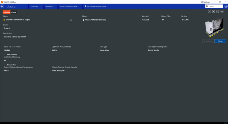
The product tab contains all of the design parameters that define the internal combustion engine.

Rated Full Load Power
|
Default Value: 170,607 Btuh [IP], 50000 W [SI]
|
|
Typical Range: -999 x1012 to 999 x1012
|
|
Min & Max: N/A
|
|
Units: Btuh, kW, W
|
Enter the design nominal capacity of the combustion turbine generator.
Optimum Part Load Ratio
|
Default Value: 100%
|
|
Typical Range:0 to 100
|
|
Min & Max: N/A
|
|
Units: %
|
This field contains the optimal fraction of full load, meaning this is the part load ratio that gives the optimal production of electricity with the least amount of fuel usage.
Fuel Type
|
Default Value: Electricity
|
|
Typical Range: -999 x1012 to 999 x1012
|
|
Min & Max: N/A
|
|
Units: Diesel, Gasoline, Natural Gas, Coal, Propane Gas, Fuel Oil #1, Fuel Oil #2
|
This field determines which fuel is consumed by the generator.
Fuel Higher Heating Value
|
Default Value: 43,500 kJ/kg
|
|
Typical Range: -999 x1012 to 999 x1012
|
|
Min & Max: N/A
|
|
Units: Btu/lb, J/kg, kJ/kg
|
This numeric field contains the higher heating value (or gross energy) of the fuel used by the generator.
Heat Recovery
Enable Heat Recovery
|
Default Value: No
|
|
Typical Range: N/A
|
|
Min & Max: N/A
|
|
Units: No, Yes
|
This toggle allows you to turn on or off heat recovery. If yes is selected, applicable energy recovery inputs will appear.
Design Heat Recovery Water Flow Rate
|
Default Value: 0 gmp, 0 m3/s
|
|
Typical Range: -999 x1012 to 999 x1012
|
|
Min & Max: N/A
|
|
Units: gpm, L/s, m3/hr, m3/s, Autosize
|
Enter the design water volumetric flow rate through the heat recovery loop.
Heat Recovery Maximum Temperature
|
Default Value: 176°F [IP], 80°C [SI]
|
|
Typical Range: -999 x1012 to 999 x1012
|
|
Min & Max: N/A
|
|
Units: °F, °C
|
This field sets the maximum temperature that this piece of equipment can produce for heat recovery. The idea behind this field is that the current models do not take temperatures into account for availability and they just pass heat around the loop without a temperature limit. This temperature limit puts an upper bound on the recovered heat and limits the max temperatures leaving the component.
As temperatures in the loop approach the maximum temperature, the temperature difference between the entering water and the surfaces in the piece of equipment becomes smaller. For the given heat recovery flow rate and that temperature difference the amount of heat recovered will be reduced, and eventually there will be no heat recovered when the entering water temperature is equal to the maximum temperature specified by the user in this field. The reduced amount of heat recovered will diminish if the temperature of the loop approach is the maximum temperature, and this will show up in the reporting. This allows the user to set the availability or the quality of the heat recovered for usage in other parts of the system or to heat domestic hot water supply.
Heat Recovery Pump Type
|
Default Value: Constant Speed Pump
|
|
Typical Range: N/A
|
|
Min & Max: N/A
|
|
Units: N/A
|
Heat Recovery Pump
|
Default Value: C90.1 CV Chilled Water Pump
|
|
Typical Range: N/A
|
|
Min & Max: N/A
|
|
Units: N/A
|
Choose which type of pump will be used for the heat recovery pump. Choose either constant or variable volume.
Exhaust Flow
Design Minimum Exhaust Temperature
|
Default Value: 302°F [IP], 150°C [SI]
|
|
Typical Range: -999 x1012 to 999 x1012
|
|
Min & Max: N/A
|
|
Units: °F, °C
|
This is the design stack saturated steam temperature of the generator and the minimum temperature the exhaust can be.
Exhaust Flow per Engine Capacity
|
Default Value: 0.00000063 (kg/s)/W
|
|
Typical Range: -999 x1012 to 999 x1012
|
|
Min & Max: N/A
|
|
Units: (kg/s)/W, (kg/hr)/W, (lb/hr)/W
|
Enter the maximum exhaust flow per unit capacity for combustion generators. This parameter sets an upper limit on exhaust gas flow and exhaust gas heat recovery for generators.
Curve tab
To define the part load conditions using unloading curves, click the curves tab of the combustion turbine library. Exhaust Temperature Curve, Total Exhaust Energy Curve, and Shaft Power Curve are all available curves that can be defined on the curves tab.