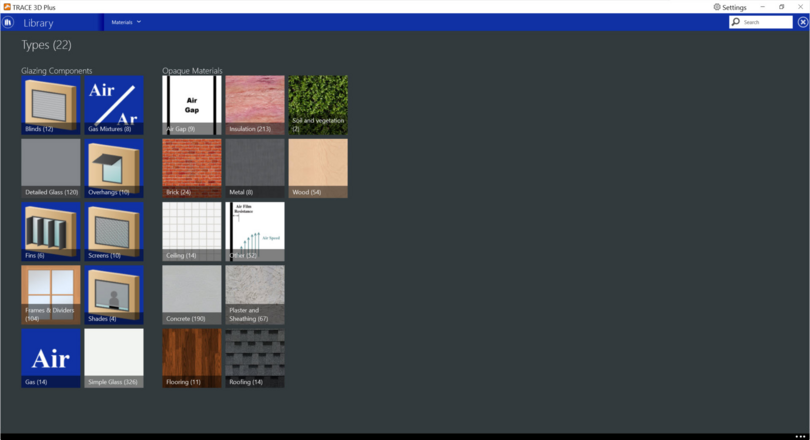
Glazing Components
Glazing components are the materials used as layers in the creation of fenestration constructions such as windows, skylights, and glass doors. The following glazing component types exist in the material library:


Blinds
 
Blinds can be added to internal or external windows, glass doors, and skylight constructions. Blinds specify the properties of a window blind consisting of flat, equally-spaced slats. Unlike window shades, which are modeled as perfect diffusers, window blinds have solar and visible transmission and reflection properties that strongly depend on slat angle and angle of incidence of solar radiation.
 
Blinds can be located on the inside of the window (“interior blinds”), on the outside of the window (“exterior blinds”), or between two layers of glass (“between glass blinds”). When in place, the blind is assumed to cover all of the glazed part of the window, including dividers; it does not cover any of the window frame, if present. The plane of the blind is assumed to be parallel to the glazing. When the blind is retracted it is assumed to cover none of the window. The solar and thermal effects of the blind’s support strings, tapes, or rods are ignored. Slat curvature, if present, is ignored.
 
The blinds library member detail screen will display the blinds properties.


Detailed Glass
 
This material type should be the preferred one for defining glass panes. “Outside” values represent the side of the glass closest to the outside air or adjacent zone and “Inside” values represent the side closest to the zone that the window is defined in.
 
The detailed glass library member detail screen will display the detailed glass properties.


Fins
 
Fin material allows you to add a vertical shading device that is attached to an external window, external glass door, or skylight construction. Fins can be placed on one or both sides of the window or door. Fin placement is relative to the edge of the glass so the frame width must be included when it is present.
 
The fins library member detail screen will display the fins properties.


Frame and Divider
 
The frame and divider material can be added to both exterior window and glass door constructions. A frame surrounds the glazing in a window as shown in the figure below. It is assumed that all frame characteristics such as width, conductance, and solar absorptance are the same for the top, bottom, and side elements of the frame. If the frame elements are not the same then you should enter area-weighted average values for the frame characteristics.
 
It is important to note that when a frame and/or divider are added to a window, the area of the glass will be reduced to fit the frame and divider.
 
EnergyPlus™ adds the frame area around the defined window vertices and automatically subtracts the area of the frame from the area of the wall containing the window.


A divider, also shown in figure above, divides the glazing into separate lites. It is assumed that all divider elements have the same characteristics. If not, area weighted average values should be used. Energy Plus automatically subtracts the divider area from the glazed area of the window.
 
The frame and divider library member detail screen will display the frame and divider properties.


Gas
 
Gas materials specify the properties of the gas that will be placed between detailed glass panes. Argon, Krypton and Xenon are available as options. There is also a “custom” option that allows you to specify the gas properties.


Gas Mixture
 
Gas mixtures allows you to specify the fill between panes of a multi-pane glazing construction with a mixture of two, three or four different gases. Air, argon, krypton and xenon are available as options. The required properties are: thickness of the gap and the percentages of each of the gas types that make up the mixture. Note that the sum of the percentages should equal 100. 


Overhangs
 
The overhang material allows you to add a horizontal shading device that is attached to an external window, external glass door, or skylight construction.
 
The overhangs library member detail screen will display the overhangs properties.


Screens
 
The window screen model assumes the screen is made up of intersecting orthogonally crossed cylinders. The surface of the cylinders is assumed to be diffusely reflecting, having the optical properties of a Lambertian surface. See figure below for a graphical representation.


The beam solar radiation transmitted through a window screen varies with sun angle and is made up of two distinct elements: a direct beam component and a reflected beam component. The direct beam transmittance component is modeled using the geometry of the screen material and the incident angle of the sun to account for shadowing of the window by the screen material. The reflected beam component is an empirical model that accounts for the inward reflection of solar beam off the screen material surface. This component is both highly directional and small in magnitude compared to the direct beam transmittance component (except at higher incident angles, for which case the magnitude of the direct beam component is small or zero and the reflected beam component, though small in absolute terms, can be many times larger than the direct beam component). For this reason, the reflected beam transmittance component calculated by the model can be a. disregarded, b. treated as an additive component to direct beam transmittance (and in the same direction), or c. treated as hemispherically diffuse transmittance based on a user input to the model.
 
The window screen “assembly” properties of overall beam solar reflectance and absorptance (including the screen material ‘cylinders’ and open area) also change with sun angle and are calculated based on the values of the beam solar transmittance components (direct and reflected components described above) and the physical properties of the screen material (i.e., screen material diameter, spacing, and reflectance). Transmittance, reflectance, and absorptance of diffuse solar radiation are considered constant values and apply to both the outside (front) and inside (back) surfaces of the screen. These properties are calculated by the model as an average value by integrating the screen’s beam solar properties over a quarter hemisphere of incident radiation. Long-wave emissivity is also assumed to be the same for both sides of the screen.
 
Window screens of this type can only be used on the outside surface of the window (“exterior screens”). When in place, the screen is assumed to cover all of the glazed part of the window, including dividers; it does not cover any of the window frames, if present. The plane of the screen is assumed to be parallel to the glazing.
 
The Screen material can be used to model wire mesh insect screens where the solar and visible transmission and reflection properties vary with the angle of incidence of solar radiation. For diffusing materials such as drapery and translucent roller shades it is better to use the Shade material. For slat type shading devices like Venetian blinds, which have solar and visible transmission and reflection properties that strongly depend on slat angle and angle of incidence of solar radiation, it is better to use Blind material.
 
The screens library member detail screen will display the screens properties.


Shades
 
Shades can be added to internal or external windows, glass doors, and skylight constructions.
 
Window shades can be on the inside of the window (“interior shades”), on the outside of the window (“exterior shades”), or between glass layers (“between-glass shades”). When in place, the shade is assumed to cover all of the glazed part of the window, including dividers; it does not cover any of the window frame, if present. The plane of the shade is assumed to be parallel to the glazing.
 
Shades can be used for diffusing materials such as drapery and translucent roller shades. For slat-type shading devices, like Venetian blinds, that have a strong angular dependence of transmission, absorption, and reflection it is better to use the Blinds material. The Screens material should be used to model wire mesh insect screens where the solar and visible transmission and reflection properties vary with the angle of incidence of solar radiation.
 
Transmittance and reflectance values for drapery material with different color and openness of weave can be obtained from manufacturers or determined from 2001 ASHRAE Fundamentals, Chapter 30, Fig. 31. Reflectance and emissivity properties are assumed to be the same on both sides of the shade. Shades are considered to be perfect diffusers (all transmitted and reflected radiation is hemispherically-diffuse) with transmittance and reflectance independent of angle of incidence.
 
The shades library member detail screen will display the shades properties.


Simple Glass
 
This material type should be used with caution. There may be significant differences in performance between glazing constructions using the simple glass layers versus detailed glass layers. It is meant to be used to describe an entire glazing system instead of creating a construction with individual layers. It should be used when very limited information is available on the glazing or when specific performance levels are being targeted.
 
The performance properties are U-factor, Solar Heat Gain Coefficient and optionally Visible Transmittance. The values for these performance indices can be selected to represent either glazing-only windows (with no frame) or an average window performance that includes the frame. 
 
The simple glass library member detail screen will display the simple glass properties.
 
When a simple glass material is referenced in a fenestration construction, it cannot be used with other glazing or gas material layers. There will be important differences in the construction performance because the simple glazing system model includes its own special model for angular dependence when incident beam solar is not normal to the plane of the window.


Glazing Component Properties
 
 
Simple glass properties
 
 
U-Factor
This field describes the U-Factor or overall heat transfer coefficient. This is the rated (NFRC) value for U-factor under winter heating conditions. The U-factor is assumed to be for vertically mounted products. Although the maximum allowable input is U-7.0 W/m2K, the effective upper limit of the glazing generated by the underlying model is around U-5.8 W/m2K.
 
Default value:
Calculated
Min & Max:
 0 < x <= 100,000
Typical Range:
1 to 7 W/(m2K); 0.01 to 1.0 to Btu/(hr °F)
Units:
W/(m2K); Btu/(hr °F)
 
 
Solar heat gain coefficient
This field describes the value for SHGC, or solar heat gain coefficient. There are no units. This is the rated (NFRC) value for SHGC under summer cooling conditions and represents SHGC for normal incidence and vertical orientation.
 
Default value:
Calculated
Min & Max:
0 < x <= 100000
Typical Range:
0.2 – 1.5
Units:
N/A
 
 
Visible transmittance
This field is optional. If it is omitted, then the visible transmittance properties are taken from the solar properties. If it is included, then the model includes it when developing properties for the glazing system. This is the rated (NFRC) value for visible transmittance at normal incidence.


Detailed glass properties
 
 
Optical Data Type
Valid values for this field in EnergyPlus™ are SpectralAverage, Spectral, and BSDF. However, only the SpectralAverage is available in the first release of TRACE 3D Plus so this field is unable to be edited. The descriptions of the other two methodologies are described below to show the different options available in EnergyPlus™.
  • If Optical Data Type = SpectralAverage, the values you enter for solar transmittance and reflectance are assumed to be averaged over the solar spectrum, and the values you enter for visible transmittance and reflectance are assumed to be averaged over the solar spectrum and weighted by the response of the human eye.
  • If Optical Data Type = Spectral, then, in the following field, you must enter the name of a spectral data set defined with the WindowGlassSpectralData object. In this case, the values of solar and visible transmittance and reflectance in the fields below should be blank.
  •  If Optical Data Type = BSDF, the Construction:ComplexFenestrationState object must be used to define the window construction layers. The Construction:ComplexFenestrationState object contains references to the BSDF files which contain the optical properties of the Complex Fenestration layers
 
Thickness
This is the surface-to-surface thickness of the glass.
Default value:
6 mm; 0.25 in.
Min & Max:
0 < x <= 100,000
Typical Range:
3 to 30 mm; 0.01 to 1.5 in
Units:
mm or in
 
 
Conductivity
It is the thermal conductivity. Valid units are W/mK or Btu/hrft°F.
Default value:
0.9 W/mK
Min & Max:
0 < x <= 100000
Typical Range:
N/A
Units:
W/mK, W/m°C, Btu/hrft°F
 
 
Solar Transmittance
Transmittance at normal incidence averaged over the solar spectrum. It is used only when Optical Data Type = Spectral Average.
Default value:
blank
Min & Max:
0 <= x <1
Typical Range:
N/A
Units:
N/A
 
 
Visible Transmittance
Transmittance at normal incidence averaged over the solar spectrum and weighted by the response of the human eye. Used only when Optical Data Type = Spectral Average.
Default value:
blank
Min & Max:
0 <= x <1
Typical Range:
N/A
Units:
N/A
 
 
Infrared Transmittance
Long-wave transmittance at normal incidence
Default value:
blank
Min & Max:
0 <= x < 1
Typical Range:
N/A
Units:
N/A
 
 
Outside and Inside Solar Reflectance
The reflectance at normal incidence averaged over the solar spectrum. Used only when Optical Data Type = Spectral Average.
Default value:
blank
Min & Max:
0 <= x < 1
Typical Range:
N/A
Units:
N/A
 
 
Outside and Inside Visible Reflectance
The reflectance at normal incidence averaged over the solar spectrum and weighted by the response of the human eye. Used only when Optical Data Type = SpectralAverage.
Default value:
blank
Min & Max:
0 <= x < 1
Typical Range:
N/A
Units:
N/A
 
 
Outside and Inside Emissivity
It is the long-wave emissivity.
Default value:
blank
Min & Max:
0 <= x < 1
Typical Range:
N/A
Units:
N/A


Gas properties
 
Gas type
This is the type of gas. The choices are Air, Argon, Krypton, or Xenon. If Gas Type = Custom, you can use the fields below for coefficients A and B to specify the properties of a different type of gas. In the following expression, the A and B coefficients give a property value as a function of temperature in degrees K:
Property = Coefficient A + Coefficient B Temperature K
 
Thickness
This is the thickness of the gas layer.
Default value:
6 mm; 0.25 in
Min & Max:
0 < x < = 100,000
Typical Range:
3 to 30 mm; 0.01 to 1.5 in
Units:
mm or in
 
 
Conductivity coefficient A
The conductivity for coefficient A.
Default value:
blank
Min & Max:
0 < x <= 100,000
Typical Range:
N/A
Units:
W/mK; W/m°C; Btu/hrft°F
 
 
Conductivity coefficient B
The conductivity for coefficient B given in W/mK2; W/m°C2; Btu/hrft°F2.
Default value:
blank
Min & Max:
0 < x <= 100,000
Typical Range:
N/A
Units:
W/mK2; W/m°C2; Btu/hr°F2
 
 
Viscosity coefficient A
The viscosity for coefficients A.
Default value:
blank
Min & Max:
0 < x <= 100,000
Typical Range:
N/A
Units:
kg/ms; lb/fts
 
 
Viscosity coefficient B
The viscosity for coefficient B
Default value:
blank
Min & Max:
0 < x <= 100,000
Typical Range:
N/A
Units:
kg/msK; lb/fts°F
 
 
Specific heat coefficient A
The specific heat for coefficient A.
Default value:
blank
Min & Max:
0 < x <= 100,000
Typical Range:
N/A
Units:
J/KgK; J/Kg•°C; Btu/lb°F
 
 
Specific heat coefficient B
The specific heat for coefficient B.
Default value:
blank
Min & Max:
0 < x <= 100,000
Typical Range:
N/A
Units:
J/KgK2; J/Kg•°C2; Btu/lb°F2
 
 
Molecular weight
The molecular weight is the mass of 1 mol of the gas substance. This has a numerical value which is the average molecular mass of the molecules in the substance multiplied by Avogadro’s constant.
Default value:
blank
Min & Max:
20 <= x <= 200
Typical Range:
N/A
Units:
g/mol; lb/mol


Frame and divider properties
 
 
Frame width
It is the width of the frame elements when projected onto the plane of the window. It is assumed that the top, bottom, and side elements of the frame have the same width. If not, an average frame width should be entered such that the projected frame area, calculated using the average value, equals the sum of the areas of the frame elements.
 
Default value:
6 mm; 0.25 in
Min & Max:
0 < x <= 500
Typical Range:
3 to 30 mm; 0.01 to 1.5 in
Units:
mm; in
 
 
Frame outside projection
It is the amount by which the frame projects outward from the outside surface of the window glazing. If the outer surface of the frame is flush with the glazing, frame outside projection = 0.0. This value is used to calculate shadowing of frame onto the glass, solar absorbed by the frame, IR emitted and absorbed by the frame and convection from the frame.
 
Default value:
blank
Min & Max:
0 < x <= 500
Typical Range:
N/A
Units:
mm; in
 
 
Frame inside projection
It is the amount by which the frame projects inward from the inside surface of the window glazing. If the inner surface of the frame is flush with the glazing, frame projection = 0.0. This value is used to calculate solar absorbed by the frame, IR emitted, and absorbed by the frame and convection from the frame.
 
Default value:
blank
Min & Max:
0 < x <= 500
Typical Range:
N/A
Units:
mm; in
 
 
Frame Conductance
The effective thermal conductance of the frame measured from inside to outside frame surface (no air films) and taking 2-D conduction effects into account. The WINDOW program is a good source for this value.
 
Default value:
blank
Min & Max:
0 < x <= 4
Typical Range:
N/A
Units:
W/m2K, W/m2°C, Btu/h°F
 
 
Ratio of frame-edge conductance to center of glass
The glass conductance near the frame (excluding air films) divided by the glass conductance at the center of the glazing (excluding air films). This value is used only for multiple glazing constructions. This ratio is greater than 1.0 because of thermal bridging from the glazing across the frame and across the spacer that separates the glass panes. The WINDOW program is a good source for this value.
 
Default value:
1
Min & Max:
0 < x <= 4
Typical Range:
N/A
Units:
N/A
 
 
Frame solar absorptance
This is the solar absorptance of the frame. The value is assumed to be the same on the inside and outside of the frame and to be independent of angle of incidence of solar radiation. If solar reflectance (or reflectivity) data is available, then absorptance is equal to 1.0 minus reflectance (for opaque materials).
 
Default value:
0.7
Min & Max:
0 <= x <= 1
Typical Range:
N/A
Units:
N/A
 
 
Frame visible absorptance
This is the visible absorptance of the frame. The value is assumed to be the same on the inside and outside of the frame and to be independent of angle of incidence of solar radiation. If visible reflectance (or reflectivity) data is available, then the absorptance is equal to 1.0 minus reflectance (for opaque materials).
 
Default value:
0.7
Min & Max:
0 <= x <= 1
Typical Range:
N/A
Units:
N/A
 
 
Thermal emissivity
This is the thermal emissivity of the frame. It is assumed to be the same on the inside and outside.
 
Default value:
0.9
Min & Max:
0 < x <= 1
Typical Range:
N/A
Units:
N/A
 
 
Divider type
The figure below shows the two types of divider.
 
 
Divider Type = Suspended is applicable only to multi-pane glazing. It means that the divider is suspended between the panes. (If there are more than two glass layers, the divider is assumed to be placed between the two outermost layers.)
 
Divider Type = Divided-Lite means the divider elements project out from the outside and inside surfaces of the glazing and divide the glazing into individual lites. For multi-pane glazing, this type of divider also has between-glass elements that separate the panes.


Divider width
This is the width of the divider elements when projected onto the plane of the window. It is assumed that the horizontal and vertical divider elements have the same width. If not, an average divider width should be entered so that the projected divider area, calculated using the average value, equals the sum of the areas of the divider elements.
 
Default value:
6 mm; 0.25 in
Min & Max:
0 <= x <= 1000
Typical Range:
3 to 30 mm; 0.01 to 1.5 in/A
Units:
mm; in
 
 
Number of horizontal dividers
This is the number of divider elements parallel to the top and bottom of the window.
 
Default value:
0
Min & Max:
0 <= x <= 1000
Typical Range:
1-5
Units:
N/A
 
 
Number of vertical dividers
The number of divider elements parallel to the sides of the window.
 
Default value:
0
Min & Max:
0 <= x <= 1000
Typical Range:
1-5
Units:
N/A
 
 
Divider outside projection
This is the amount by which the divider projects out from the outside surface of the window glazing. For Divider Type = Suspended, the Divider Projection = 0.0. It is used to calculate shadowing of divider onto the glass, solar absorbed by the divider, IR emitted and absorbed by the divider, and convection from the divider.
 
Default value:
blank
Min & Max:
0 <= x <= 500
Typical Range:
N/A
Units:
mm; in
 
 
Divider inside projection
This is the amount by which the divider projects inward from the inside surface of the window glazing. If the inner surface of the divider is flush with the glazing, the Divider inside Projection = 0.0. It is used to calculate solar absorbed by the divider, IR emitted and absorbed by the divider, and convection from the divider.
 
Default value:
blank
Min & Max:
0 < x <= 1000
Typical Range:
N/A
Units:
mm; in
 
 
Divider conductance
The effective thermal conductance of the divider measured from inside to outside divider surface (no air films) and taking 2-D conduction effects into account. The WINDOW program is a good source for this value.
 
Default value:
blank
Min & Max:
0 < x <= 100,000
Typical Range:
N/A
Units:
W/m2K, W/m2°C, Btu/h°F
 
 
Ratio of divider-edge conductance to center of glass
The glass conductance near the divider (excluding air films) divided by the glass conductance at the center of the glazing (excluding air films). It is used only for multi-pane glazing constructions. This ratio is greater than 1.0 because of thermal bridging from the glazing across the divider and across the spacer that separates the glass panes. The WINDOW program is a good source for this value.
 
Default value:
1
Min & Max:
0 < x <= 4
Typical Range:
N/A
Units:
N/A
 
 
Divider solar absorptance
This is the solar absorptance of the divider. The value is assumed to be the same on the inside and outside of the divider and to be independent of angle of incidence of solar radiation. If solar reflectance (or reflectivity) data is available, then absorptance is equal to 1.0 minus reflectance (for opaque materials).
 
Default value:
blank
Min & Max:
0 < x <= 1
Typical Range:
N/A
Units:
N/A
 
 
Divider visible absorptance
This is the visible absorptance of the divider. The value is assumed to be the same on the inside and outside of the divider and to be independent of angle of incidence of solar radiation. If visible reflectance (or reflectivity) data is available, then absorptance is equal to 1.0 minus reflectance (for opaque materials).
 
Default value:
blank
Min & Max:
0 < x <= 1
Typical Range:
N/A
Units:
N/A
 
 
Divider thermal emissivity
This is the thermal emissivity of the divider, assumed the same on the inside and outside.
 
Default value:
blank
Min & Max:
0 < x < 1
Typical Range:
N/A
Units:
N/A
 
 
Is the  window flush with the wall?
 
The fields below are active if the window has a reveal (is not flush with the wall). From this information and from the geometry of the window and the sun position, the program calculates beam solar radiation absorbed and reflected by the top, bottom, right and left sides of outside and inside window reveal surfaces. In doing this calculation, the shadowing on a reveal surface by other reveal surfaces is determined using the orientation of the reveal surfaces and the sun position.
It is assumed that:
  • The window is an exterior window.
  • The reveal surfaces are perpendicular to the window plane.
  • If an exterior shade, screen or blind is in place it shades exterior and interior reveal surfaces so that in this case there is no beam solar on these surfaces.
  • If an interior shade or blind is in place it shades the interior reveal surfaces so that in this case there is no beam solar on these surfaces.
  • The possible shadowing on inside reveal surfaces by a window divider is ignored.
  • The outside reveal surfaces (top, bottom, left, right) have the same solar absorptance and depth. This depth is not input here but is automatically determined by the program—from window and wall vertices-as the distance between the plane of the outside face of the glazing and plane of the outside face of the parent wall.
  • The inside reveal surfaces are divided into two categories: (1) the bottom reveal surface, called here the "inside sill;" and (2) the other reveal surfaces (left, right and top).
  • The left, right and top inside reveal surfaces have the same depth and solar absorptance. The inside sill is allowed to have depth and solar absorptance values that are different from the corresponding values for the other inside reveal surfaces.
  • The inside sill depth is required to be greater than or equal to the depth of the other inside reveal surfaces. If the inside sill depth is greater than zero the depth of the other inside reveal surfaces is required to be greater than zero.
  • The reflection of beam solar radiation from all reveal surfaces is assumed to be isotropic diffuse; there is no specular component.
  • Half of the beam solar reflected from outside reveal surfaces goes towards the window; the other half goes back to the exterior environment (i.e., reflection of this outward-going component from other outside reveal surfaces is not considered).
  • The half that goes towards the window is added to the other solar radiation incident on the window. Correspondingly, half of the beam solar reflected from inside reveal surfaces goes towards the window, with the other half going into the zone. The portion going towards the window that is not reflected is absorbed in the glazing or is transmitted back out into the exterior environment.
  • The beam solar that is absorbed by outside reveal surfaces is added to the solar absorbed by the outside surface of the window's parent wall; similarly, the beam solar absorbed by the inside reveal surfaces is added to the solar absorbed by the inside surface of the parent wall.
 
The net effect of beam solar reflected from outside reveal surfaces is to increase the heat gain to the zone, whereas the effect of beam solar reflected from inside reveal surfaces is to decrease the heat gain to the zone since part of this reflected solar is transmitted back out the window. If the window has a frame, the absorption of reflected beam solar by the inside and outside surfaces of the frame is considered. The shadowing of the frame onto interior reveal surfaces is also considered.
The figure below shows a graphic representation of the reveal values.
 
 
Outside reveal solar absorptance
This is the solar absorptance of outside reveal surfaces.
 
Default value:
blank
Min & Max:
0 < x <= 1
Typical Range:
N/A
Units:
N/A
 
 
Inside sill depth
This is the depth of the inside sill, measured from the inside surface of the glazing to the edge of the sill.
 
Default value:
blank
Min & Max:
0 <= x <= 2000
Typical Range:
N/A
Units:
mm; in
 
 
Inside sill solar absorptance
This is the solar absorptance of the inside sill.
 
Default value:
blank
Min & Max:
0 < x <= 1
Typical Range:
N/A
Units:
N/A
 
 
Inside reveal depth
This is the depth of the inside reveal surfaces other than the sill, measured from the inside surface of the glazing to the edge of the reveal surface.
 
Default value:
blank
Min & Max:
0 <= x <= 2000
Typical Range:
N/A
Units:
mm; in


Inside reveal solar absorptance
This is the solar absorptance of the inside reveal surfaces other than the sill.
 
Default value:
blank
Min & Max:
0 < x <= 1
Typical Range:
N/A
Units:
N/A


Shades properties
 
Solar transmittance
This is the transmittance averaged over the solar spectrum. It is assumed independent of incidence angle.
Default value:
blank
Min & Max:
0 <= x < 1
Typical Range:
N/A
Units:
N/A
 
 
Solar reflectance
This is the reflectance averaged over the solar spectrum. It is assumed the same on both sides of the shade and independent of incidence angle.
 
Default value:
blank
Min & Max:
0 <= x < 1
Typical Range:
N/A
Units:
N/A
 
 
Visible transmittance
This is the transmittance averaged over the solar spectrum and weighted by the response of the human eye. It is assumed independent of incidence angle.
 
Default value:
blank
Min & Max:
0 <= x < 1
Typical Range:
N/A
Units:
N/A
 
 
Visible reflectance
This is the reflectance averaged over the solar spectrum and weighted by the response of the human eye. It is assumed the same on both sides of the shade and independent of incidence angle.
 
Default value:
blank
Min & Max:
0 <= x < 1
Typical Range:
N/A
Units:
N/A
 
 
Thermal emissivity
This is the effective long-wave emissivity. It is assumed the same on both sides of the shade. We can approximate this effective emissivity, εeff, as follows. Let η be the “openness” the shade, i.e., the ratio of the area of openings in the shade to the overall shade area. Let the emissivity of the shade material be ε. Then: εeff ≈ ε (1 − η). For most non-metallic materials ε is about 0.9.
 
Default value:
blank
Min & Max:
0 <= x < 1
Typical Range:
N/A
Units:
N/A
 
 
Thermal transmittance
This is the effective long-wave transmittance. It is assumed independent of the incidence angle. We can approximate this effective long-wave transmittance, Teff, as follows. Let η be the “openness” the shade, i.e., the ratio of the area of openings in the shade to the overall shade area. Let the long-wave transmittance of the shade material be T. Then: Teff ≈ η + T (1 − η). For most materials, T is very close to zero, which gives Teff ≈ η.
 
Default value:
blank
Min & Max:
0 <= x < 1
Typical Range:
N/A
Units:
N/A
 
 
Thickness
This is the thickness of the shade material (m). If the shade is not flat, such as for pleated pull-down shades or folded drapery, the average thickness normal to the plane of the shade should be used.
Default value:
6 mm; 0.25 in
Min & Max:
0 <= x < 1000
Typical Range:
3 to 30 mm; 0.01 to 1.5 in
Units:
mm; in
 
 
Conductivity
This is the shade material conductivity.
Default value:
0.9 W/mK
Min & Max:
0 < x <= 100,000
Typical Range:
N/A
Units:
W/mK; W/m°C; Btu/hrft°F


Blinds properties
 
Type
The choices are horizontal and vertical. “Horizontal” means the slats are parallel to the bottom of the window; this is the same as saying that the slats are parallel to the X-axis of the window. “Vertical” means the slats are parallel to Y-axis of the window.
The figure below shows a graphic representation of blind properties.


Slat width
This is the width of the slat measured from edge to edge.
Default value:
blank
Min & Max:
0 <= x <= 1000
Typical Range:
3 to 30 mm; 0.01 to 1.5 in
Units:
mm; in
 
 
Slat separation
This is the distance between the front of a slat and the back of the adjacent slat.
Default value:
blank
Min & Max:
0 <= x <= 1000
Typical Range:
3 to 30 mm; 0.01 to 1.5 in
Units:
mm; in
 
 
Slat thickness
This is the distance between the faces of a slat.
Default value:
0.0006 mm; 0.00025 in
Min & Max:
0 < x <= 1000
Typical Range:
3 to 30 mm; 0.01 to 1.5 in
Units:
mm; in
 
 
Slat angle
This is the angle (degrees) between the glazing outward normal and the slat outward normal, where the outward normal points away from the front face of the slat (degrees).
Default value:
45 degrees
Min & Max:
0 <= x <= 180
Typical Range:
30 to 60
Units:
degrees
 
 
Slat conductivity
This is the thermal conductivity for the slat.
Default value:
221 W/mK
Min & Max:
0 <= x <= 100,000
Typical Range:
N/A
Units:
W/mK; Btu/hrft°F
 
 
Slat beam solar transmittance
This is the beam solar transmittance of the slat. It is assumed to be independent of the angle of incidence on the slat. Any transmitted beam radiation is assumed to be 100% diffuse (i.e., slats are translucent).
Default value:
blank
Min & Max:
0 <= x < 1
Typical Range:
N/A
Units:
N/A
 
 
Outside slat beam solar reflectance
This is the beam solar reflectance of the outside (front) side of the slat. It is assumed to be independent of the angle of incidence (matte finish). This means that slats with a large specularly-reflective component (shiny slats) are not well modeled.
Default value:
blank
Min & Max:
0 <= x < 1
Typical Range:
N/A
Units:
N/A
 
 
Inside slat beam solar reflectance
This is the beam solar reflectance of the inside (back) side of the slat. It is assumed to be independent of the angle of incidence (matte finish). This means that slats with a large specularly-reflective component (shiny slats) are not well modeled.
Default value:
blank
Min & Max:
0 <= x < 1
Typical Range:
N/A
Units:
N/A
 
 
Slat beam visible transmittance
This is the beam visible transmittance of the slat. It is assumed to be independent of angle of incidence on the slat. Any transmitted visible radiation is assumed to be 100% diffuse (i.e., slats are translucent).
Default value:
blank
Min & Max:
0 <= x < 1
Typical Range:
N/A
Units:
N/A
 
 
Outside slat beam visible reflectance
This is the beam visible reflectance on the outside (front) side of the slat. It is assumed to be independent of angle of incidence (matte finish). This means that slats with a large specularly-reflective component (shiny slats) are not well modeled.
Default value:
blank
Min & Max:
0 <= x < 1
Typical Range:
N/A
Units:
N/A
 
 
Inside slat beam visible reflectance
This is the beam visible reflectance on the inside (back) side of the slat. It is assumed to be independent of angle of incidence (matte finish). This means that slats with a large specularly-reflective component (shiny slats) are not well modeled.
Default value:
blank
Min & Max:
0 <= x < 1
Typical Range:
N/A
Units:
N/A
 
 
Infrared hemispherical transmittance
This is the slat Infrared transmittance. It is zero for solid metallic, wooden or glass slats, but may be non-zero in some cases (e.g., thin plastic slats).
Default value:
blank
Min & Max:
0 <= x < 1
Typical Range:
N/A
Units:
N/A
 
 
Minimum closing angle
This is the minimum allowed slat angle in degrees. It is only used the shading control for the window varies with the slat angle. See Window constructions for more information.
Default value:
blank
Min & Max:
0 <= x <= 180
Typical Range:
N/A
Units:
degrees
 
 
Maximum opening angle
This is the maximum allowed slat angle in degrees. It is only used the shading control for the window varies with the slat angle. See Window constructions for more information.
Default value:
blank
Min & Max:
0 <= x <= 180
Typical Range:
N/A
Units:
degrees


Screens properties
 
 
Method used for beam solar reflection
This input specifies the method used to account for screen-reflected beam solar radiation that is transmitted through the window screen (as opposed to being reflected back outside the building). Since this inward reflecting beam solar is highly directional and is not modeled in the direction of the actual reflection, you have the option of how to account for the directionality of this component of beam solar transmittance. Valid choices are Do not model, Model as direct beam (i.e., model as an additive component to direct solar beam and in the same direction), or Model as diffuse (i.e., model as hemisphericallydiffuse radiation). The default value is Model as diffuse.
 
 
Solar reflectance
This input specifies the solar reflectance (beam-to-diffuse) of the screen material itself (not the effective value for the overall screen “assembly” including open spaces between the screen material). The outgoing diffuse radiation is assumed to be Lambertian (distributed angularly according to Lambert’s cosine law). The solar reflectance is assumed to be the same for both sides of the screen. This value must be from 0 to less than 1.0. In the absence of better information, the input value for diffuse solar reflectance should match the input value for diffuse visible reflectance.
 
Default value:
blank
Min & Max:
0 <= x < 1
Typical Range:
N/A
Units:
N/A
 
 
Visible reflectance
This input specifies the visible reflectance (beam-to-diffuse) of the screen material itself (not the effective value for the overall screen “assembly” including open spaces between the screen material) averaged over the solar spectrum and weighted by the response of the human eye. The outgoing diffuse radiation is assumed to be Lambertian (distributed angularly according to Lambert’s cosine law). The visible reflectance is assumed to be the same for both sides of the screen. This value must be from 0 to less than 1.0.
 
If diffuse visible reflectance for the screen material is not available, then the following guidelines can be used to estimate this value:
 
Dark-colored screen (e.g., charcoal): 0.08 – 0.10
Medium-colored screen (e.g., gray): 0.20 – 0.25
Light-colored screen (e.g., bright aluminum): 0.60 – 0.65
 
Default value:
0.25
Min & Max:
0 <= x < 1
Typical Range:
N/A
Units:
N/A
 
 
Strand spacing
The spacing, S, of the screen material (m) is the distance from the center of one strand of screen to the center of the adjacent one. The spacing of the screen material is assumed to be the same in both directions (e.g., vertical and horizontal). This input value must be greater than the non-zero screen material diameter. If the spacing is different in the two directions, use the average of the two values. See image below for a graphic representation.
 
 
Default value:
blank
Min & Max:
0 <= x <= 1000
Typical Range:
N/A
Units:
mm; in
 
 
Diameter of strands
This is the diameter, D, of individual strands or wires of the screen material. The screen material diameter is assumed to be the same in both directions (e.g., vertical and horizontal). This input value must be greater than 0 and less than the screen material spacing. If the diameter is different in the two directions, use the average of the two values. See image above for a graphic representation.
 
Default value:
blank
Min & Max:
0 <= x <= 1000
Typical Range:
N/A
Units:
mm; in
 
 
Emissivity
Long-wave emissivity ε of the screen material itself (not the effective value for the overall screen “assembly” including open spaces between the screen material). The emissivity is assumed to be the same for both sides of the screen. For most non-metallic materials,  ε is about 0.9. For metallic materials, ε is dependent on material, its surface condition, and temperature. Typical values for metallic materials range from 0.05 – 0.1 with lower values representing a more finished surface (e.g. low oxidation, polished surface). Material emissivities may be found in Table 5 from the 2005 ASHRAE Handbook of Fundamentals, page 3.9. The value for this input field must be between 0 and 1, with a default value of 0.9 if this field is left blank.
 
Default value:
0.9
Min & Max:
0 < x < 1
Typical Range:
N/A
Units:
N/A
 
 
Conductivity
This is the screen material conductivity in W/mK or Btu/hr-ft-F. This input value must be greater than 0.
 
Default value:
221 W/mK
Min & Max:
0 <= x <= 100,000
Typical Range:
N/A
Units:
W/mK; Btu/hrft°F


Overhangs properties
 
Height above window
This field is the height above the top of the window or door for the overhang.
Default value:
blank
Min & Max:
0 <= x <= 100,000
Typical Range:
N/A
Units:
mm; in
 
 
Tilt angle
This field is the tilt angle from the window or door. For a flat overhang, this would be 90 degrees.
Default value:
90 degrees
Min & Max:
0 <= x <= 180
Typical Range:
N/A
Units:
degrees
 
 
Left extension
This field is the width from the left edge of the window or door to the start of the overhang.
 
Default value:
blank
Min & Max:
0 <= x <= 100,000
Typical Range:
N/A
Units:
mm; in
 
 
Right extension
This field is the width from the right edge of the window or door to the start of the overhang.
Default value:
blank
Min & Max:
0 <= x <= 100,000
Typical Range:
N/A
Units:
mm; in
 
 
Projection out
This field is the depth of the overhang projecting out from the wall.
Default value:
blank
Min & Max:
0 <= x <= 100,000
Typical Range:
N/A
Units:
mm; in


Fins properties
 
Left and Right extension above window
This field is the width from the left or right edge of the window/door to the plane of the left or right fin. The extension width is relative to the edge of the glass and includes the frame width when a frame is present.
Default value:
blank
Min & Max:
0 <= x <= 100,000
Typical Range:
N/A
Units:
mm; in
 
 
Left and Right distance above top of window
This field is the distance from the top of the window to the top of the fin and is relative to the edge of the glass and includes the frame width when a frame is present.
Default value:
blank
Min & Max:
0 <= x <= 100,000
Typical Range:
N/A
Units:
mm; in
 
 
Left and Right distance below top of window
This field is the distance from the bottom of the window to the bottom of the fin and is relative to the edge of the glass and includes the frame width when a frame is present.
Default value:
blank
Min & Max:
0 <= x <= 100,000
Typical Range:
N/A
Units:
mm; in
 
 
Left and Right tilt angle
This field is the tilt angle from the window / door for the fin. Typically, a fin is 90 degrees (default) from its associated window/door.
Default value:
90 degrees
Min & Max:
0 <= x <= 180
Typical Range:
N/A
Units:
degrees
 
 
Left and Right depth
This field is the depth of the fin projecting out from the wall.
Default value:
blank
Min & Max:
0 <= x <= 100,000
Typical Range:
N/A
Units:
mm; in