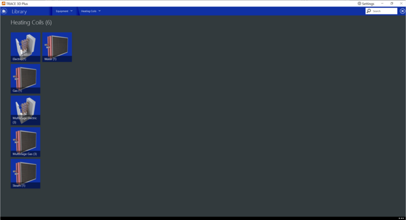
Trace 3D Plus
User Guide
 
×


Heating Coils
 
In this library, you can create several different heating coils. Below are the types of coils you can create:
 
 
*See the Reference page for resources used in the help documentation.
 
 
Electric Coils
 
Nominal Heating Capacity
Default: Auto sized
Typical Range: NA
Min Max: 0 to 999,999
Units: W, kW, tons, Btuh
This is the maximum capacity of the coil. This controlled coil will only provide the needed capacity to meet the control criteria whether it is temperature or capacity controlled. This field is autosizable.
 
Efficiency
Default: 100%
Typical Range: 100%
Min Max: 0 to 100
Units: NA
This is user-inputted efficiency (decimal units, not percent) and can account for any loss. In most cases for the electric coil, this will be 100%.
*See the Reference page for resources used in the help documentation.


Multi-Stage Electric
The multi stage electric heating coil is a simple capacity model with a user-inputted efficiencies at different stages. In many cases, the efficiencies for the electric coil will be 100%. The coil can be used in the air system or in the zone equipment as a reheat coil. Depending on where it is used determines if this coil is temperature or capacity controlled. If used in the air loop system it will be controlled to a specified temperature scheduled from the controller. If it is used in zone equipment, it will be controlled from the zone thermostat by meeting the zone demand.
 
Number of Stages
Default: 2
Typical Range: 1 to 3
Min Max: 0 to 999,999,999
Units: NA
This is the maximum capacity of the coil. This controlled coil will only provide the needed capacity to meet the control criteria whether it is temperature or capacity controlled. This field is autosizable.
 
Nominal Heating Capacity (Each Stage)
Default: Auto sized
Typical Range: NA
Min Max: 0 to 999,999,999
Units: W, kW, tons, Btuh
This is the maximum capacity of the coil. This controlled coil will only provide the needed capacity to meet the control criteria whether it is temperature or capacity controlled. This field is autosizable.
 
Efficiency (Each Stage)
Default: 100%
Typical Range: 100%
Min Max: 0 to 100
Units: NA
This is user-inputted efficiency (decimal units, not percent) and can account for any loss. In most cases for the electric coil, this will be 100%.
 
 
*See the Reference page for resources used in the help documentation.


Gas
The fuel heating coil is a simple capacity model with a user inputted gas burner efficiency. The default for the burner efficiency is 80%. The coil can be used in the air loop system or in the zone equipment as a reheat coil. Depending on where it is used determines if this coil is temperature or capacity controlled. If used in the air loop system it will be controlled to a specified temperature scheduled from the setpoint controller. If it is used in zone equipment, it will be controlled from the zone thermostat by meeting the zone demand.
 
Product tab
Nominal Capacity
Default: Auto sized
Typical Range: NA
Min Max: 0 to 0999,999,999
Units: W, kW, tons, Btuh
This is the maximum capacity of the coil. This controlled coil will only provide the needed capacity to meet the control criteria whether it is temperature or capacity controlled. This field is autosizable.
 
Full Load Efficiency
Default: 90%
Typical Range: N/A
Min Max: 0 to 100
Units: %
This numeric field accounts for any efficiency losses at full load for the selected stage, where for example 100% full load
efficiency (field input of 100) would account for no losses.
 
Parasitic Electric Load
Default: 0 W
Typical Range: NA
Min Max: 0.000 to 1,000,000,000,000,000
Units: W, kW, Btuh, Mbh
This is the parasitic electric load associated with the coil operation, such as an inducer fan, etc. This will be modified by the part-load ratio to reflect the time of operation in a simulation timestep.
 
Parasitic Gas Load
Default: 0.000 W
Typical Range: NA
Min Max: -1,000,000,000,000,000 to 1,000,000,000,000,000
Units: W, kW, Btuh, Mbh
This numeric field is the parasitic fuel load associated with the coil’s operation, such as a standing pilot light. The model assumes that this parasitic load is consumed only for the portion of the simulation timestep where the heating coil is not operating.
*See the Reference page for resources used in the help documentation.
 
 
Curve tab
Part Load Fraction Correlation Curve
This curve parameterizes the variation of fuel consumption rate by the heating coil as a function of the part load ratio (part load ratio, sensible heating load/nominal capacity of the heating coil). For any simulation timestep, the nominal fuel consumption rate (heating load/burner efficiency) is divided by the part-load fraction if a part-load curve has been defined. The part-load curve accounts for efficiency losses due to transient coil operation.
If part load fraction < 0.7 a warning message is issued during simulation and the program resets the part load fraction value to 0.7, and the simulation proceeds.


Multistage Gas
The fuel heating coil is a simple capacity model with a user inputted gas burner efficiency at different stages. The coil can be used in the air loop system or in the zone equipment as a reheat coil. Depending on where it is used determines if this coil is temperature or capacity controlled. If used in the air loop system it will be controlled to a specified temperature scheduled from the setpoint controller. If it is used in zone equipment, it will be controlled from the zone thermostat by meeting the zone demand.
 
Product tab
Nominal Capacity (Different Stages)
Default: Auto size
Typical Range: NA
Min Max: 0 to 999,999,999
Units: W, kW, tons, Btu
This is the maximum capacity of the coil. This controlled coil will only provide the needed capacity to meet the control criteria whether it is temperature or capacity controlled. This field is autosizable.
 
Full Load Efficiency (Different Stages)
Default: 100%
Typical Range: 80 to 95%
Min Max: 0 to 100
Units: NA
This is user-inputted efficiency (decimal units, not percent) and can account for any loss.
 
Parasitic Electric Load (Different Stages)
Default: 0 W
Typical Range: NA
Min Max: 0 to 999,999,999
Units: W, kW, HP
This is the parasitic electric load associated with the coil operation, such as an inducer fan, etc. This will be modified by the part-load ratio to reflect the time of operation in a simulation timestep.
 
 
Parasitic Gas Load (Different Stages)
Default: 0 W
Typical Range: NA
Min Max: 0 to 999,999,999
Units: W, kW, Btu, Mbh
This numeric field is the parasitic fuel load associated with the coil’s operation, such as a standing pilot light. The model assumes that this parasitic load is consumed only for the portion of the simulation timestep where the heating coil is not operating.
 
Curve tab
Part Load Fraction Correlation Curve
This curve parameterizes the variation of fuel consumption rate by the heating coil as a function of the part load ratio (part load ratio, sensible heating load/nominal capacity of the heating coil). For any simulation timestep, the nominal fuel consumption rate (heating load/burner efficiency) is divided by the part-load fraction if a part-load curve has been defined. The part-load curve accounts for efficiency losses due to transient coil operation.
If part load fraction < 0.7 a warning message is issued during simulation and the program resets the part load fraction value to 0.7, and the simulation proceeds.
 
*See the Reference page for resources used in the help documentation.


Steam
The simple steam to air heating coil model only does sensible heating of the air. The steam to air coils condenses the steam and sub cools steam at loop pressure and discharges the condensate through steam traps at low pressure condensate line.
 
Condensate Sub Cool - Coil
Default: 41°F/5°C
Typical Range: NA
Min Max: 35.6 to 999,999,999
Units: °F/°C
Ideally the steam trap located at the outlet of steam coil should remove all the condensate immediately, however there is a delay in this process in actual systems which causes the condensate to SubCool by certain degree in the coil before leaving the coil, this SubCool occurs in the steam coil and this SubCool-heat is added to the zone.
 
Condensate Sub Cool - Loop
Default: 68°F/20°C
Typical Range: NA
Min Max: 50 to 999,999,999
Units: °F/°C
This essentially represents the heat loss to the atmosphere due to uninsulated condensate return piping to the boiler. Condensate return piping operates at atmospheric pressure and is not insulated. The condensate sub cools to certain degree before it is pumped back to the boiler.
 
*See the Reference page for resources used in the help documentation.


Water
This simple heating coil model only does sensible heating of the air. The simple heating coil uses the Effectiveness-NTU algorithm and assumes a cross-flow heat exchanger.
 
Calculation Method
Default: Capacity
Typical Range: NA
Min Max: NA
Units: NA
The user can choose either UAMethod or Capacity. If UAMethod is selected, the user must input values for UA of the Coil (and Rated Capacity is ignored). If Capacity is chosen, the user must input a Rated Capacity for the coil. Rated capacity is defined as the heating capacity in watts of the coil at the rating points (i.e., the rated inlet and outlet water/air temperatures defined in the input fields below). The rated capacity is used to calculate a water mass flow rate and a UA for the coil.
To autosize the capacity, choose UAMethod and put autosize as the inputs for U-Factor Times Area Value and Rated Capacity. The program will use the Sizing inputs to size the coil. The rated temperatures are ignored in autosizing. These are used only when the user is specifying coil performance using the NominalCapacity input method.
 
Rated Heating Capacity
Default: Auto size
Typical Range: NA
Min Max: 0 to 999,999,999
Units: W, kW, Btuh, Mbh
The heating capacity of the coil in watts at the rated inlet and outlet air and water temperatures. The gross rated heating capacity does not account for the effect of supply air fan heat. This field is used when the Performance Input Method = Nominal Capacity. This field is autosizable.
 
Rated Water Inlet Temperature
Default: 180°F/82.2°C
Typical Range: 150°F to 200°F
Min Max: 0 to 999,999,999
Units: °F/°C
The inlet water temperature corresponding to the rated heating capacity.
 
Rated Air Inlet Temperature
Default: 60.98°F/16.6°C
Typical Range: 55°F to 70°F
Min Max: 0 to 999,999,999
Units: °F/°C
The inlet air temperature corresponding to the rated heating capacity.
 
Rated Water Outlet Temperature
Default: 159.98°F/71.1°C
Typical Range: 130°F to 170°F
Min Max: 0 to 999,999,999
Units: °F/°C
The outlet water temperature corresponding to the rated heating capacity.
 
Rated Air Inlet Temperature
Default: 89.96°F/32.2°C
Typical Range: 80°F to 100°F
Min Max: 0 to 999,999,999
Units: °F/°C
The outlet air temperature corresponding to the rated heating capacity.
 
Rated Evaporation Ratio
Default: 0.5
Typical Range: 0.5 to 0.6
Min Max: 0 to 1
Units: NA
This is the ratio of convective heat transfers between air side and water side of the heating coil at the rated operating conditions. This ratio describes the geometry and the design of the coil and is defined by:
where:
 
ηf is the fin efficiency, (dimensionless)
h is the surface convection heat transfer coefficient
A is the surface area
 
 
*See the Reference page for resources used in the help documentation.