Trace 3D Plus
User Guide
 
×


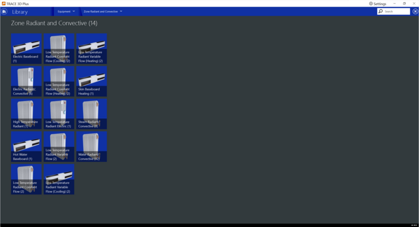
Zone Radiant and Convective
Radiant and Convective equipment are zone level devices used to condition HVAC in individual zones. There are several types of zone radiant and convective equipment in this library:


Electric Baseboard
The electric baseboard heater is a device used to meet any remaining zone load not met by other equipment in the zone that have higher heating priority.
 
Nominal Heating Capacity
Default: Auto Size
Typical Range: Auto Size
Min Max: 0 < X
Units: W, W/ft2, W/m2, Btuh, Mbh, tons, Btuh/ft2, kW, % of Htg capacity 
This field specifies the convective electric baseboard nominal heating capacity.
 
Full Load Efficiency
Default: 90%
Typical Range: N/A
Min Max: 0 to 100%
Units: %
This is the overall electrical efficiency of the electric baseboard. The zone load met by this unit is divided by the electrical efficiency to obtain the total electric energy used.


Electric Radiant/Convective
The electric radiant/convective heater, radiates heat to people and surfaces and also uses convection for the surrounding air. The electric baseboard model includes the impact of the radiant heat addition to people and surfaces so that the thermal comfort and surface heat balances are impacted. The component is controlled to meet any remaining zone load not met by other equipment in the zone that have higher heating priority.
 
Nominal Heating Capacity
Default: Auto Size
Typical Range: Auto Size
Min Max: 0 < X
Units: W, W/ft2, W/m2, Btuh, Mbh, tons, Btuh/ft2, kW, % of Htg capacity 
This field specifies the convective electric baseboard nominal heating capacity.
 
Full Load Efficiency
Default: 90%
Typical Range: N/A
Min Max: 0 to 100%
Units: %
This is the overall electrical efficiency of the electric baseboard. The zone load met by this unit is divided by the electrical efficiency to obtain the total electric energy used.
 
Radiant
Default: 50%
Typical Range: 20 to 80%
Min Max: 0 to 100%
Units: %
This field specifies what fraction of the power input to the baseboard heater is actually transferred to the space as radiant heat. The fraction should be between 0% and 100%. This is the portion of the total power that is modeled as radiation. The radiant heat transfer from the baseboard heater to people should not be included in this field.
 
Radiant Incident on people
Default: 50%
Typical Range: N/A
Min Max: 0 to 100%
Units: %
This field specifies the fraction of the radiant portion of heat transfer to the zone from the baseboard heater that is incident directly on people within the space. This has an impact on the predicted thermal comfort of the zone occupants. Note that although this energy is “radiant” it is actually modeled in the zone heat balance as a convective energy (like an internal gain). The basic assumption here is that radiant energy falling on people will most likely be released again to the zone air by convection. This is a simplification of reality, but it maintains the overall energy balance.
*Note that the sum of both fields the Radiant and the Radiant Incident on People should equal 100% so that all the radiant power is distributed properly.
 
 
High Temperature Radiant
The high temperature radiant system (gas-fired or electric) is a zone equipment that is intended to model any “high temperature” or “high intensity” radiant system where electric resistance or gas-fired combustion heating is used to supply energy (heat) to a building occupants directly as well as the building surfaces (wall, ceiling, or floor). The component does not require the use of a zone thermostat unless the unit is being autosized. If the radiant system is serving a zone with forced air equipment, the radiant system will follow the priority order established by the zone thermostat but will still base its response on the controls defined by the user for the radiant system. The control is accomplished by varying the electrical power supplied to or gas consumed by the unit. This is not intended to simulate low temperature electric or hydronic radiant systems.
 
Nominal Heating Capacity
Default: Autosize
Typical Range: Autosize
Min Max: 0 < x
Units: W, W/ft2, W/m2, Btuh, Mbh, tons, Btuh/ft2, kW, % of Htg capacity, tons/ft2
This field is for the maximum amount of electric energy rate (electric power) converted into heat in the high temperature radiant electric unit. This input field is auto sizable. The controls for the radiant system will vary the amount of power supplied to the surface between zero input and the maximum power specified in this field as the lower and upper bounds, respectively. Note that if the user elects to autosize this field, a standard zone thermostat must be defined as autosizing.
 
Radiant
Default: 50%
Typical Range: 20 to 80%
Min Max: 0 to 100%
Units: %
This field specifies what fraction of the power input to the high temperature radiant heater is actually transferred to the space as radiant heat. The fraction should be between 0% and 100%. This is the portion of the total power that is modeled as radiation.
 
Latent
Default: 40%
Typical Range: 20 to 80%
Min Max: 0 to 100%
Units: %
This field specifies the fraction of the power input to the high temperature radiant heater that is converted to a latent heat gain within the space. This may be appropriate when a combustion process produces moisture that is transferred into the space. The latent heat addition from a high temperature radiant heater is handled as any other latent heat gain within the space, affecting the moisture balance on the zone air.
 
Lost
Default: 10%
Typical Range: 10 to 20%
Min Max: 0 to 100%
Units: %
This field specifies the fraction of power input to the high temperature radiant heater that is “lost”. This energy is a loss term, and this fraction of the input power has no effect on the zone heat balances.
 
*Note: The sum of these fractions must be less than or equal to 1. If the fractions are less than one, the remaining energy is added to the zone as convective heat transfer. The radiant heat transfer from the heat is distributed to people using the Radiant Incident on people.
 
Fuel Type
Default: Natural Gas
Typical Range: Natural Gas, Electricity
Min Max: N/A
Units: N/A
This field denotes the type of high temperature radiant heater: gas or electric.
 
Combustion Efficiency
Default: 100%
Typical Range: 20 to 80%
Min Max: 0 to 100%
Units: %
This field is the combustion efficiency for a gas high temperature radiant heater. It is intended to take into account any potential inefficiencies in the combustion process inside the radiant heater. The heater gas consumption is the ratio of heater output over the combustion efficiency. This field is not available when the Fuel Type is “Electricity”.
 
Radiant Incident on people
Default: 10%
Typical Range: N/A
Min Max: 0 to 100%
Units: %
This field specifies the fraction of the radiant portion of heat transfer to the zone from the radiant heater that is incident directly on people within the space. This has an impact on the predicted thermal comfort of the zone occupants. Note that although this energy is “radiant” it is actually modeled in the zone heat balance as a convective energy (like an internal gain). The basic assumption here is that radiant energy falling on people will most likely be rereleased to the zone air by convection. This is a simplification of reality, but it maintains the overall energy balance.
 
Temperature Control
Control Type
Default: Mean Air Temperature
Typical Range: N/A
Min Max: N/A
Units: N/A
This field specifies how the user wishes to control the high temperature radiant system. The user must select from the following options:
       Mean Air Temperature
       Mean Radiant Temperature
       Operative Temperature
       Mean Air Temperature – Detailed
       Mean Radiant Temperature - Detailed
       Operative Temperature – Detailed
 
Heating Range
Default: 3.6
Typical Range: N/A
Min Max: 0 <= x
Units: Delta F, Delta C
This field specifies the range of temperature over which the radiant system throttles through the electric resistance from zero heat input up to the maximum specified in the Nominal Heat Capacity field. The Heating Range parameter is used in conjunction with the Setpoint Temperature Type to define the response of the system to various zone conditions. The field Setpoint Temperature specifies the temperature where the power input to the system is at half of the maximum power input. For example, if the Setpoint Temperature is currently 15°C and the heating throttling range is 2°C, the electrical power supplied to the radiant system will be zero when the controlling temperature is at or above 16°C and the maximum power input when the controlling temperature is at or below 14°C. This represents a throttling range of 2°C around the setpoint of 15°C. In between 14°C and 16°C, the power input to the radiant system is varied linearly.
 
Setpoint Temperature Type
Default: Constant
Typical Range: N/A
Min Max: Constant, Variable
Units: N/A
This field specifies the type of heating setpoint for the radiant system. Used in conjunction with the Heating Range field, it will define whether or not the system is running and the current power input to the radiant surface. Power input to the system is varied linearly around the setpoint temperature based on the Heating Range and the maximum electrical power parameters. The field Setpoint Temperature specifies the temperature where the power input to the system is at half of the maximum power input. For example, if the Setpoint Temperature is currently 15°C and the heating range is 2°C, the electrical power supplied to the radiant system will be zero when the controlling temperature is at or above 16°C and the maximum power input when the controlling temperature is at or below 14°C. This represents a heating range of 2°C around the setpoint of 15°C. In between 14°C and 16°C, the power input to the radiant system is varied linearly.
 
 
Constant Setpoint Temperature / Variable Setpoint Temperature
Default: 55°F, 13°C
Typical Range: N/A
Min Max: N/A
Units: °F, °C
This field specifies the heating setpoint for the radiant system depending on the Setpoint Temperature type. For a Constant type, the user should enter a Constant Setpoint Temperature. For a variable type, the user can select a setpoint schedule from the menu.
 
 
Hot Water Baseboard
The hot water baseboard heater is a zone equipment used to meet any remaining zone load not met by other equipment in the zone that have higher heating priority. The unit is connected to a hot water loop (demand side) with an inlet and outlet node.
 
 
Nominal Heating Capacity
Default: Auto Size
Typical Range: Auto Size
Min Max: 0 < x
Units: W, W/ft2, W/m2, Btuh, Mbh, tons, tons/ft2, Btuh/ft2, kW, % of Htg capacity
This field specifies the water baseboard heater nominal heating capacity. This field can be autosized.
 
UA (U-Factor times Area Value)
Default: Auto Size
Typical Range: Auto Size
Min Max: -999 to 999
Units: W/°F, W/°C, W/K
This field specifies the heat transfer coefficient for the baseboard heater at design conditions. The UA factor is used in a Number of Transfer Units (NTU) calculation.
An estimate of the UA can be obtained from:
q = UA x (T water, avg - T air,avg)
Where:
q = heat transferred from water to the air (Watts)
Twater, avg = average water temperature
Tair, avg = average air temperature


Low Temperature Radiant Constant Flow (Cooling and/or Heating)
A Low Temperature Radiant panel is a zone level heating and/or cooling coil mounted in the floor, walls, and/or ceiling of the rooms. In TRACE 3D Plus, the Low Temperature Radiant Constant Flow equipment is zone level equipment that uses water to heat and/or cool a room surface (floor or ceiling). A constant flow system uses a separate zone level circulation pump to maintain constant flow.
A Ceiling Radiant Panel must be assigned to a zone that contains rooms with radiant layers in their ceiling construction. An In Floor Radiant Panel must be assigned to a zone that contains rooms with radiant layers in their floor construction.
The heating and/or cooling is controlled by varying the water temperature to the coil(s). The water temperature to the coil(s) is varied by the use of a three-way mixing valve upstream of the pump which allows a fraction of the return water to mix with supply water. The Low Temperature Radiant Constant Flow equipment uses a water loop from a separate plant and are not themselves directly heated by gas or electric: there are separate library members for Low Temperature Radiant Electric panels and High Temperature Radiant panels.
 
Control Type
Default: Mean Air Temperature
Typical Range: N/A
Min Max:N/A
Units: N/A
The Control Type field specifies which parameter the Setpoint Temperature High Limit and Setpoint Temperature Low Limit fields represent. The Setpoint Temperature limits and the Water Inlet Temperature limits together control the constant flow radiant system. The Control Type field must be set to one of the following options:
  • Mean Air Temperature
  • Mean Radiant Temperature
  • Operative Temperature
  • Outdoor Dry Bulb Temperature
  • Outdoor Wet Bulb Temperature
 
Cooling Mode/Heating Mode
Low Temperature Radiant Constant Flow equipment may be configured as cooling only, heating only, or heating and cooling. The water flow rate is based upon the operating mode. If the unit operates in cooling only or heating only, the heating or cooling design flow rate is selected. If the unit operates in heating and cooling, the largest value between the heating design flow rate and the cooling design flow rate is selected.
 
Water Inlet Temperature High/Low limit
Default: 59°F/15°C (High), 50°F/ 10°C (Low)
Typical Range: 50° to 59°F / 10° to 15°C
Min Max: 75 to 120°F / 23.8 to 48.8°C
Units: °F/°C
The Water Inlet Temperature High and Low Limit fields specify the high and low limits for the mixed water temperature leaving the three-way valve and entering the coil(s). If the water temperatures from the plant and from the coil(s) are such that mixing water to meet these limits is not possible, an error will occur.
 
Setpoint Temperature High/Low Limit
Default: 79°F/26.11°C (High), 72°F/ 22.22°C (Low)
Typical Range: 72° to 79°F/22° to 26°C
Min Max: N/A
Units: °F/°C
The Setpoint Temperature High Limit and Low Limit fields specify the high and low limits for the temperature of the parameter specified in the Control Type field.
The Setpoint Temperature limits for the Control Type field and the Water Inlet Temperature limits together control the constant flow radiant system.The current temperature of the parameter specified in the Control Type field is compared to the Setpoint Temperature High Limit and Low Limit at the current time.
 
Control in Cooling Mode
  • If the current temperature of the parameter specified in the Control Type field is above the Setpoint Temperature High Limit, the mixed water temperature will be set to the Water Inlet Temperature Low Limit.
  • If the current temperature of the parameter specified in the Control Type field is between the Setpoint Temperature High Limit and Low Limit, the mixed water temperature will be modulated between the Water Inlet Temperature Low Limit and High Limit.
  • If the current temperature of the parameter specified in the Control Type field is below the Setpoint Temperature Low Limit, the water flow rate will be set to zero to shut down the pump and coil(s).
 
Control in Heating Mode
  • If the current temperature of the parameter specified in the Control Type field is below the Setpoint Temperature Low Limit, the mixed water temperature will be set to the Water Inlet Temperature High Limit.
  • If the current temperature of the parameter specified in the Control Type field is between the Setpoint Temperature Low Limit and High Limit, the mixed water temperature will be modulated between the Water Inlet Temperature High Limit and Low Limit.
  • If the current temperature of the parameter specified in the Control Type field is above the Setpoint Temperature High Limit, the water flow rate will be set to zero to shut down the pump and coil(s).
 
Secondary Pump
The secondary pump provides the water flow through the low temperature radiant coil(s). The pump will consume energy as it provides the water flow rate according to the inputs provided.
 
Full Load Power
Default: 50 W
Typical Range: N/A
Min Max: > 0 W
Units: W, kW, hp
The Full Load Power field specifies the total full load input power.
 
Pump Head
Default: 25 ft H2O
Typical Range: 5 to 36 ft H2O
Min Max: NA
Units: ft H2O, Pa, kPa
This field contains the pump’s rated head.
 
Motor Efficiency
Default: 80%
Typical Range: N/A
Min Max: 0 to 100%
Units: %
Enter the pump’s efficiency
 
Motor Heat to Fluid
Default: 0%
Typical Range: N/A
Min Max: 0 to 100%
Units: %
This field contains the pump’s percentage of power loss to the fluid.
 
 
Condensation
Control Type
Default: System Off
Typical Range: System Off, Moisture Control
Min Max: N/A
Units: N/A
When radiant systems do cooling, there is the possibility that condensation will occur on the surface that is being cooled. This is due to the fact that the surface temperature may drop below the dew-point temperature of the space which causes condensation to accumulate on the surface.
The Control Type field can be set to either No Moisture Control or System Off.
  • No Moisture Control – TRACE 3D Plus will nothing other than produce a warning message when condensation is predicted to occur. The program will continue: no moisture will be removed from the zone air and no adjustment will be made to the surface temperature as a result of the condensation.
  • System Off – TRACE 3D Plus will predict cases where condensation will occur and shut-off the radiant system to avoid this situation. With this option, the user has the ability to adjust when the system will shut down using the Dewpoint Range field.
 
Dewpoint Range
Default: 34°F/1.11°C
Typical Range: 50 to 59°F / 10 to 16°C
Min Max: 0 to 100°F / -17 to 38°C
Units: °F/°C
This optional parameter is only available when the System Off option is selected for the Control Type. It establishes the difference between the calculated dew-point temperature of the space and the allowed surface temperature to which the surface can drop before the radiant system shuts down. This parameter can be any positive, negative, or zero value. When this parameter is zero, the radiant system will shut down when the surface temperature drops to the dew-point temperature or below. When this parameter is positive, the radiant system will shut down when the surface is the number of degrees above the dewpond temperature; this allows some extra safety to avoid condensation. When this parameter is negative, the radiant system will shut down when the surface temperature is the number of degrees below the dew-point temperature. While not recommended, this strategy allows the user to simulate a situation where small amounts of condensation are tolerable.
 
Hydronic Tubing
Diameter
Default: 0.51 in/0.013 m
Typical Range: 50 to 59°F / 10 to 16°C
Min Max: NA
Units: ft, in/m, cm, mm
This field is the inside diameter of the tubes through which water is circulated for the system. The inside diameter is used to determine the convective heat transfer from the water to the inside surface of the hydronic tubing.
 
Length
Default: Autosize
Typical Range: N/A
Min Max: > 0
Units: ft, in/m, cm, mm
This field is the total length of pipe embedded in the surface. The length of the tube is used to determine the effectiveness of heat transfer from the fluid being circulated through the tubes and the tube/surface. Longer tubing lengths result in more heat being transferred to/from the radiant surface to the circulating fluid. This field is auto sizable.
 
Circuit
Circuit Length Method
Default: Autocalculate
Typical Range: N/A
Min Max: One per surface, Autocalculate
Units: N/A
This optional input allows the user to choose between modeling each surface in the radiant system as a single hydronic circuit or to allow the program to divide the surface into multiple parallel hydronic circuits based on the input field Circuit Length. To model as a single circuit choose One Per Surface. To model as multiple circuits choose Autocalculate which is the default option.
 
Circuit Length
Default: 350 ft/106.7 m
Typical Range: N/A
Min Max: 0
Units: ft, in/m, cm, mm
This field represents the length of each parallel hydronic circuit in a surface. It is only available when the circuit length method is set to Auto calculate.
 
 
Low Temperature Radiant Electric
The Low Temperature Radiant Electric equipment is a zone level piece of equipment that is intended to model any “radiant system” where electric resistance heating is used on a surface (wall, ceiling, or floor).
A Ceiling Radiant Panel must be assigned to a zone that contains rooms with radiant layers in their ceiling construction. An In Floor Radiant Panel must be assigned to a zone that contains rooms with radiant layers in their floor construction.
The heating is controlled by varying the electrical power supplied to the unit. This model covers either a radiant panel system or wires embedded in entire walls, floors, or ceilings. This equipment group should not be used to simulate High Temperature Radiant electric or gas radiant heaters.
 
Nominal Heating Capacity
Default: Autosize
Typical Range: Autosize
Min Max: N/A
Units: Btuh, Mbh, tons, tons/ft2, Btuh/ft2, W, W/ft2, W/m2, kW, % of Htg capacity
This field specifies the maximum amount of electric energy rate (electric power) converted into heat. This input field is auto sizable. The controls for the radiant system will vary the amount of power supplied to the surface between zero input and the maximum power specified in this field.
 
Temperature Control
Control type
Default: Mean Air Temperature
Typical N/A
Min Max: N/A
Units: N/A
This Control Type field specifies how the user wishes to control the Heating Range of the   low temperature radiant electric system. The temperature specified in the Constant setpoint Temperature field can refer to one of the following different temperatures selected in the Control Type field:• MeanAirTemperature
  • Mean Air Temperature
  • Mean Radiant Temperature
  • Operative Temperature
  • Outdoor DryBulb Temperature
  • Outdoor WetBulb Temperature
 Note: Operative temperature for radiant system controls is the average of Mean Air Temperature and Mean Radiant Temperature..
 
Heating Range
Default: 3.6 Delta °F
Typical Range: N/A
Min Max: x > 0.5 Delta °C
Units: Delta °F, Delta °C, Delta °R, Delta °K
This field specifies the range of temperature over which the radiant system throttles through the electric resistance from zero heat input up to the maximum specified in the Nominal Heating Capacity field. The Heating Range parameter is used in conjunction with the Constant Setpoint Temperature Type to define the response of the system to various zone conditions. The field Constant Setpoint Temperature specifies the temperature where the power input to the system is at half of the maximum power input. For example, if the Constant Setpoint Temperature is currently 15°C and the Heating Range is 2°C, the electrical power supplied to the radiant system will be zero when the controlling temperature is at or above 16°C and the maximum power input when the controlling temperature is at or below 14°C. This represents a throttling range of 2°C around the setpoint of 15°C. In between 14°C and 16°C, the power input to the radiant system is varied linearly.
 
Setpoint Temperature Type
Default: Constant
Typical Range: N/A
Min Max: Constant, Variable
Units: N/A
This field specifies the type of heating setpoint for the radiant system. Used in conjunction with the Heating Range field, it will define whether or not the system is running and the current power input to the radiant surface. Power input to the system is varied linearly around the setpoint temperature based on the Heating Range and the maximum electrical power parameters. The field Setpoint Temperature specifies the temperature where the power input to the system is at half of the maximum power input. For example, if the Constant Setpoint Temperature is currently 15°C and the Heating Range is 2°C, the electrical power supplied to the radiant system will be zero when the controlling temperature is at or above 16°C and the maximum power input when the controlling temperature is at or below 14°C. This represents a heating range of 2°C around the setpoint of 15°C. In between 14°C and 16°C, the power input to the radiant system is varied linearly.
 
Constant/Variable Setpoint Temperature
Default: 55°F (constant)/Null (variable)
Typical Range: N/A
Min Max: N/A
Units: ºF, °C
This field specifies the heating setpoint for the radiant system depending on the Setpoint Temperature type. For a Constant type, the user should enter a Constant Setpoint Temperature. For a Variable type, the user can select a setpoint schedule from the menu.
 
 
Low Temperature Radiant Variable Flow Cooling and/or Heating
A Low Temperature Radiant panel is a zone level heating and/or cooling coil mounted in the floor, walls, and/or ceiling of the rooms. The Low Temperature Radiant Variable Flow equipment is zone level equipment that uses water to heat and/or cool a room surface (floor or ceiling).  If the radiant system is serving a zone with forced air equipment, the radiant system will follow the priority order established by the zone thermostat but will still base its response on the controls defined by the user for the radiant system.
A Ceiling Radiant Panel must be assigned to a zone that contains rooms with radiant layers in their ceiling construction. An In Floor Radiant Panel must be assigned to a zone that contains rooms with radiant layers in their floor construction.
The heating and/or cooling is controlled by throttling the hot or chilled water flow to the unit. The temperature remains constant while the flow increases or decreases to meet the load.  The Low Temperature Radiant Variable Flow equipment uses a water loop from a separate plant and are not themselves directly heated by gas or electric: there are separate library members for Low Temperature Radiant Electric panels and High Temperature Radiant panels.
 
 
Control Type
Default: Mean Air Temperature
Typical Range: N/A
Min Max: N/A
Units: N/A
This field specifies along with the water temperatures and setpoint temperatures how the user wishes to control the hydronic radiant system. The temperature denoted in the Setpoint Temperature fields can refer to one of five different temperatures: the zone mean air temperature, the zone mean radiant temperature, the zone operative temperature, the outdoor dry-bulb temperature, or the outdoor wet-bulb temperature. The user must select from the following options:
  • Mean Air Temperature
  • Mean Radiant Temperature
  • Operative Temperature
  • Outdoor DryBulb Temperature
  • Outdoor WetBulb Temperature
Note: Operative temperature for radiant system controls is the average of Mean Air Temperature and Mean Radiant Temperature.
 
Operating Modes
Low Temperature Radiant Variable Flow equipment may be configured as cooling only, heating only, or heating and cooling. The temperature difference is based upon the operating mode. If the unit operates in cooling only or heating only, the heating or cooling temperature range is selected.
 
 Cooling Mode
Nominal Cooling Capacity
CDefault: Autosize
Typical Range: Autosize
Min Max: 0 < x
Units: Btuh, Mbh, tons, tons/ft2, Btuh/ft2, W, W/ft2, W/m2, kW, % of Clg capacity
This field specifies the maximum or nominal cooling capacity. This input field is auto sizable. The controls for the radiant system will vary the amount of power supplied to the surface between zero input and the maximum power specified in this field.
 
Cooling Range
CDefault: 0.9
Typical Range: N/A
Min Max: N/A
Units: Delta °F, Delta °C, Delta °R, Delta K
This field specifies the range of temperature over which the radiant system operates. This range operates with the Cooling Setpoint Temperature Difference field to define the response of the system to various zone conditions.
 
Cooling Setpoint Temperature Difference
Default: 1.8
Typical Range: N/A
Min Max: N/A
Units: Delta °F, Delta °C, Delta °R, Delta K
This field specifies the temperature difference with the zone setpoint. It is used in conjunction with the Cooling Range to define whether or not the system is running and what the current flow rate is. Water flow rate to the system is varied linearly around the setpoint temperature based on the Cooling Range and the maximum cooling flow rate that the program defines.
 
Heating Mode
Nominal Heating Capacity
Default: Autosize
Typical Range: Autosize
Min Max: N/A
Units: Btuh, Mbh, tons, tons/ft2, Btuh/ft2, W, W/ft2, W/m2, kW, % of Htg capacity
This field specifies the maximum or nominal heating capacity. This input field is auto sizable. The controls for the radiant system will vary the amount of power supplied to the surface between zero input and the maximum power specified in this field.
 
Heating Range
Default: 0.9
Typical Range: N/A
Min Max: 0 < x
Units: Delta °F, Delta °C, Delta °R, Delta K
This field specifies the range of temperature over which the radiant system operates. This range operates with the Heating Setpoint Temperature Difference field to define the response of the system to various zone conditions.
 
Heating Setpoint Temperature Difference
Default: 1.8
Typical Range: N/A
Min Max:N/A
Units: Delta °F, Delta °C, Delta °R, Delta K
This field specifies the temperature difference with the zone setpoint. It is used in conjunction with the Heating Range to define whether or not the system is running and what the current flow rate is. Water flow rate to the system is varied linearly around the setpoint temperature based on the Cooling Range and the maximum cooling flow rate that the program defines.
 
Condensation
Control Type
Default: System Off
Typical Range: System Off, No Moisture Control
Min Max: N/A
Units: N/A
When radiant systems do cooling, there is the possibility that condensation will occur on the surface that is being cooled. This is due to the fact that the surface temperature may drop below the dew-point temperature of the space which causes condensation to accumulate on the surface.
The Control Type field can be set to either No Moisture Control or System Off.
  • No Moisture Control – TRACE 3D Plus will nothing other than produce a warning message when condensation is predicted to occur. The program will continue: no moisture will be removed from the zone air and no adjustment will be made to the surface temperature as a result of the condensation.
  • System Off – TRACE 3D Plus will predict cases where condensation will occur and shut-off the radiant system to avoid this situation. With this option, the user has the ability to adjust when the system will shut down using the Dewpoint Range field.
 
Dewpoint Range
Default: 34°F/1.11°C
Typical Range: 50 to 59°F / 10 to 16°C
Min Max: 0 to 100°F/-17 to 38°C
Units: °F/°C
This optional parameter is only available when the System Off option is selected for the Control Type. It establishes the difference between the calculated dew-point temperature of the space and the allowed surface temperature to which the surface can drop before the radiant system shuts down. This parameter can be any positive, negative, or zero value. When this parameter is zero, the radiant system will shut down when the surface temperature drops to the dew-point temperature or below. When this parameter is positive, the radiant system will shut down when the surface is the number of degrees above the Dewpoint temperature. This allows some extra safety to avoid condensation. When this parameter is negative, the radiant system will shut down when the surface temperature is the number of degrees below the dew-point temperature. While not recommended, this strategy allows the user to simulate a situation where small amounts of condensation are tolerable.
 
Hydronic Tubing
Diameter
Default: 0.51 in/0.13 m
Typical Range: N/A
Min Max: x > 0
Units: ft, in/m, cm, mm
This field is the inside diameter of the tubes through which water is circulated for the system. The inside diameter is used to determine the convective heat transfer from the water to the inside surface of the hydronic tubing.
 
Length
Default: Autosize
Typical Range: N/A
Min Max: x > 0
Units: ft, m
This field is the total length of pipe embedded in the surface. The length of the tube is used to determine the effectiveness of heat transfer from the fluid being circulated through the tubes and the tube/surface. Longer tubing lengths result in more heat being transferred to/from the radiant surface to the circulating fluid. This field is auto sizable.
 
 
Circuit
Circuit Length Method
Default: Autocalculate
Typical Range: N/A
Min Max: One per surface, Autocalculate
Units: N/A
This optional input allows the user to choose between modeling each surface in the radiant system as a single hydronic circuit or to allow the program to divide the surface into multiple parallel hydronic circuits based on the input field Circuit Length. To model as a single circuit choose One Per Surface. To model as multiple circuits choose Autocalculate which is the default option.
 
Circuit Length
Default: 350 ft/106.7 m
Typical Range: N/A
Min Max: > 0
Units: ft, in/m, cm, mm
This field represents the length of each parallel hydronic circuit in a surface. It is only available when the circuit length method is set to Auto calculate.
 
 
Skin Baseboard Heating
The Skin Baseboard Heating is zone level electric heating equipment.  This object specifies that the baseboard heating will control in reaction to the outside temperature. The capacities (high and low) are specified at the temperature field next to each one of them. This baseboard heater does not operate if the outdoor dry bulb is above the high temperature limit. Between the high temperature and the low temperature, the capacity is interpolated (linear) between the high and the low capacity values. Below the low temperature, the capacity is set at the low capacity value. This allows the user to add baseboard heat to a perimeter zone starting at a prescribed temperature and then slowly increases this capacity to a max value.  The maximum capacity would correspond to the low temperature.
 
Nominal Heating Capacity at High temperature
Default: 0 Btuh/0 W
Typical Range: x > 0
Min Max: N/A
Units: Btuh, kW, MBh, tons, W
This field represents the baseboard equipment capacity at the high temperature limit.
 
High temperature
Default: 60°F/15°C
Typical Range: x > Low Temperature
Min Max: N/A
Units: °F/°C
This field limits the operation of the Baseboard Heater. If the outdoor dry-bulb temperature is greater than the high temperature, the baseboard heater will not operate.
 
Radiant
Default: 50%
Typical Range: 0 < x < 100
Min Max: N/A
Units: %
This field is used to characterize the quantity of radiant heat being given off by baseboard heat equipment to a zone. The number specified in this field will be multiplied by the total energy consumed by the baseboard heat equipment. This will provide the amount of long wavelength radiation gain to the zone.
 
Low Temperature
Nominal Heating Capacity
Default: 0 Btuh/0 W
Typical Range: x > Nominal Heating Capacity at High temperature
Min Max: N/A
Units:: Btuh, kW, MBh, tons, W
This field represents the baseboard equipment capacity at the low temperature limit.
 
Low temperature
Default: -4°F/-20°C
Typical Range: x < Low Temperature
Min Max: N/A
Units: °F/°C
This field limits the operation of the Baseboard Heater. If the outdoor dry-bulb temperature is at or below the low temperature, the baseboard heater operates at the low temperature capacity.
 
 
Steam Radiant / Convective
This zone level equipment calculates the convective and radiant heat transfer from steam baseboard heaters to the people and the surfaces within the assigned zone. Surface heat balances can thus take into account the radiant heat transfer to the surfaces in order to enhance the accuracy of thermal comfort predictions within the space.
 
Nominal Heating Capacity
Default: Autosize
Typical Range: x > 0
Min Max: N/A
Units: % Htg Capacity, Btuh, Btuh/ft2, kW, MBh, tons, tons/ft2, W, W/ft2, W/m2
This field represents the maximum radiant/convective steam baseboard unit heating capacity. The program will calculate this capacity if Autosize is selected.
 
Radiant
Default: 50%
Typical Range: 0 < X < 100
Min Max: N/A
Units: %
This field specifies what percentage of the total power input to the baseboard heater is transferred to the space as radiant heat. The portion that is radiant heat transfer from the baseboard heater is distributed to people and specific surfaces.
 
Radiant Incident on People
Default: 50%
Typical Range: 0 < X < 100
Min Max: N/A
Units: %
This field specifies the percentage of radiant portion of heat transfer to the zone from the baseboard heater that is incident directly on people within the space. This has an impact on the predicted thermal comfort of the zone occupants. The basic assumption here is that most radiant energy falling on people will most likely be re-released to the zone air by convection.  Note that the sum of the percentage of all radiant energy must equal 100% so the remainder of the energy that doesn’t get absorbed by people will impact the zone surfaces.
 
Degree of Subcooling
Default: 9 Delta °F
Typical Range: x > 1
Min Max: N/A
Units: Delta °F/ Delta °C
This field is the temperature drop of the condensate in the coil of the baseboard heater. The steam condensates in the coil and changes the phase to the water, giving up the latent heat of steam to the air in the steam to air heat exchanger. The condensate, due to the phase change, then cools by certain degree in the coil.  This amount of heat is added to the zone.


Water Radiant / Convective
The water radiant/convective equipment is a zone level hot water baseboard heater unit  It calculates the convective and radiant heat transfer from water baseboard heaters to the people and the surfaces within a zone. The radiant heat gains are distributed to the surfaces by percentages defined by the user.
 
Nominal Heating Capacity
Default: Autosize
Typical Range: x > 0
Min Max: x > 0
Units: % Htg Capacity, Btuh, Btuh/ft2, kW, MBh, tons, tons/ft2, W, W/ft2, W/m2
This field represents the radiant/convective water baseboard unit heating capacity.
 
Radiant
Default: 50%
Typical Range: 50%
Min Max: 0 to 100%
Units: %
This field specifies what percentage of the power input to the baseboard heater is actually transferred to the space as radiant heat. This is the portion of the total power that is modeled as radiation.The portion that is radiant heat transfer from the baseboard heater is distributed to people and specific surfaces.
 
Radiant Incident on People
Default: 50%
Typical Range: 50%
Min Max: 0 to 100%
Units: %
This field specifies the percentage of radiant portion of heat transfer to the zone from the baseboard heater that is incident directly on people within the space. This has an impact on the predicted thermal comfort of the zone occupants. The basic assumption here is that most radiant energy falling on people will most likely be re-released to the zone air by convection. This is a simplification of reality, but it maintains the overall energy balance. Note that the sum of the percentage of all radiant energy must equal 100% so the remainder of the energy that doesn’t get absorbed by people will impact the zone surfaces.
 
Rated Avg. Water Temperature
Default: 190°F / 87.7°C
Typical Range: 150°F to 239°F / 65.56°C to 115.36°C
Min Max: 68°F to 302°F / 20°C to 150°C
Units: °F/°C
This field is the rated average water temperature for the baseboard heater which can be found in the manufacturer’s literature.
 
Rated Water Mass Flow
Default: 1 gpm / 0.063 Kg/s
Typical Range: 1 to 4gpm / 0.063 to 0.252Kg/s
Min Max: N/A
Units: gpm, Kg/hr, Kg/s
This field is the rated standard water flow rate which can be found in the manufacturer’s literature.