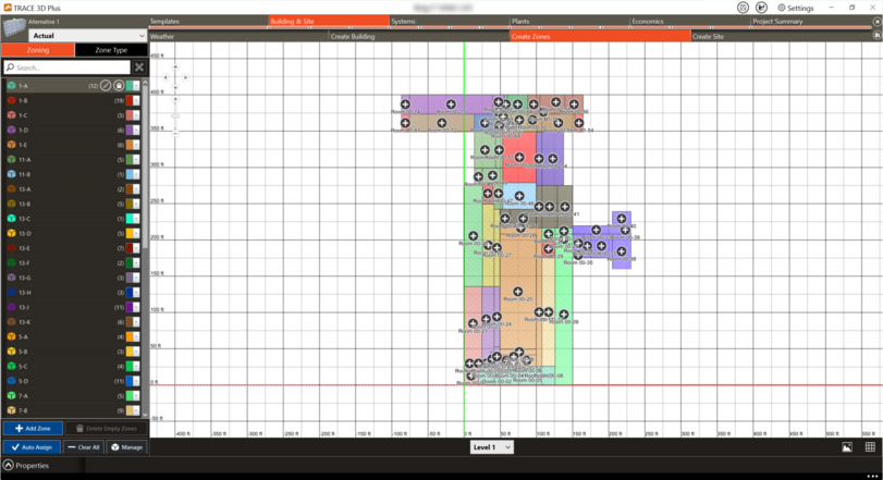
Create Zones
Rooms need to be assigned to thermal Zones. They can be auto assigned which means that each room will be its own zone or different rooms can be assigned to a zone through the Zone Manager. Different properties may vary per Zone type which can also be determined on the Zone Type tab.
|
Zoning
|
Zone Type
|
Canvas
|
|
|
|
|
|
Zone controls
|
|
|
Properties
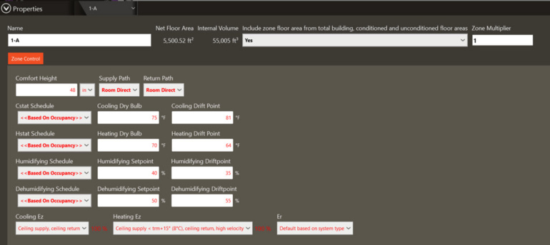
Name
This field provides the unique name of a zone.
Net Floor Area
Net floor area of the zone based on floor area of constituent rooms. This field is not editable in Zone Properties. The floor area may only be edited by altering spaces in the Drawing Canvas.
Internal Volume
The internal volume of the zone based on the constituent room heights and net floor areas. This field is not editable.
Unconditioned space
An unconditioned zone will not receive any cooling or heating from the system to which it is assigned.
Additionally, lighting and miscellaneous loads are calculated, but the zone temperature is allowed to drift. The unconditioned zones's maximum and minimum temperatures are assumed to be the Cooling Driftpoint and Heating Driftpoint temperatures.
Unconditioned zones are not factored into the unmet load hours calculation.
An unconditioned zone may impact a conditioned zone if the ceiling or underfloor plenum is shared with a conditioned zone or if the conditioned and unconditioned zones are connected via an adjacent airflow, partition, or exposed floor.
Zone Control Tab
In this section you will set the thermostat set points and drift points.
|
|
|
Comfort Height
|
Default Value: 48 inches, 1.1 meters
|
|
Typical Range: N/A
|
|
Min & Max: N/A
|
|
Units: in, ft, yd, mi, mm, cm, m, km, um
|
The height in meters above the floor at which air temperature is calculated for comfort purposes. The air temperature at this height is used in calculating the available measures of comfort: Fanger, Pierce or KSU. The default is 1.1 meters.
Supply Path
Choose from Room Direct or Plenum supply air paths. Note this setting applies to main systems delivering air through a terminal device. Also note that you want to make sure your space(s) have ceiling and/or floor plenums if you set the supply path to plenum.
Room Direct
Supply air is delivered directly to the space (i.e. ducted).
Plenum
Supply air is dumped into the plenum and supplied through a diffuser to the space.
Return Path
Select the path through which the return air is routed back to the main cooling/heating coils. In all cases, the return air eventually passes through the return/outside air deck. Also note that you want to make sure your space(s) have ceiling and/or floor plenums if you set the return path to plenum.
Room Direct
Return air conditions are equal to the room conditions (i.e. room air is recirculated through the main coil like fan coils).
Plenum
The return air will pick up any heat from roofs, walls, and lights that are assigned to the return air, although a portion of this plenum load may conduct back into the room or outdoors.
Cstat Schedule
There are two ways to define the cooling thermostat schedule:
● The first method is to use the Schedule Utility (Library/Template editors) to define a cooling thermostat profile and then enter the schedule code name in this field.
● The second method is to leave this field blank: the setup temperature from the Cooling driftpoint will then apply during the hours in which the People Schedule reads 5% or less; the cooling set point will equal the design room cooling dry bulb during the hours in which the People Schedule reads greater than 5%.
This field is ignored by the design calculation.
Cooling Dry Bulb
This value represents the thermostat set point for the zone during cooling design calculations. It is used to calculate room cooling loads, design cooling coil capacities, and design fan capacities.
During the System phase, if the Cooling Thermostat Schedule is left as "Based On Occupancy", the cooling thermostat will try to control the zone to this temperature. whenever the People schedule reads greater than 5%.
Cooling Drift Point
The cooling thermostat driftpoint is the highest temperature that the room is allowed to drift up to during periods of low or no occupancy. (This is also referred to as the cooling setup temperature.) If the room temperature starts to rise above this value, the available cooling equipment will be activated to allow cooling of this room. If Cooling Schedule is selected as“Based on Occupancy”, the program will allow the room to drift up to the setup temperature during the hours in which the People Schedule reads 5% or less; if the People Schedule reads greater than 5%, the cooling thermostat will try to control the room to the design room cooling dry-bulb.
The Cooling thermostat driftpoint has no effect on the design calculation and is ignored by the system calculation if a cooling thermostat schedule is defined.
Hstat Schedule
There are two ways to define the heating thermostat schedule:
● The first method is to use the Schedule Utility (Library/Template editors) to define a heating thermostat profile and then enter the schedule code name in this field.
● The second method is to leave this field blank: the setback temperature from the Heating driftpoint will then apply during the hours in which the People Schedule reads 5% or less; the heating setback will equal the design room heating dry bulb during the hours in which the People Schedule reads greater than 5%
This field is ignored by the design calculation.
Heating Dry Bulb
This value represents the thermostat set point for the zone during heating design calculations. It is used to calculate room heating loads, design heating coil capacities, and design fan capacities.
During the System phase, if the Heating Thermostat Schedule is left as "Based On Occupancy", the heating thermostat will try to control the zone to this temperature. whenever the People schedule reads greater than 5%.
Heating Drift Point
The heating thermostat driftpoint is the lowest temperature that the room is allowed to drift down to during periods of low or no occupancy. (This is also referred to as the heating setback temperature.) If the room temperature starts to fall below this value, the available heating equipment will be activated to allow heating of this room. If Heating Schedule is selected as “Based on Occupancy”, the program will allow the room to drift down to the setback temperature during the hours in which the People Schedule reads 5% or less; if the People Schedule reads greater than 5%, the cooling thermostat will try to control the room to the design room cooling dry-bulb.
The heating thermostat driftpoint has no effect on the design calculation and is ignored by the system calculation if a heating thermostat schedule is defined.
Cooling and Heating Ez
|
Default Value: Per ASHRAE 62.1-2010 table 6-2 depending on the Air Distribution Configuration
|
|
Typical Range: 0.5 to 1.2
|
|
Min & Max: N/A
|
|
Units: N/A
|
The Zone air distribution effectiveness is a measure of how thoroughly the cooling supply airflow mixes with the air in the breathing zone (which is basically the air up to six feet above the floor).
This effectiveness is based on the location of the supply and return air grilles, the velocity of the airflow, and the proximity of the makeup air grille to the exhaust air grille. The available values are from table 6-2 of ASHRAE Standard 62.1- 2010 depending on the type of air distribution for the room.
Er
|
Default Value: 0
|
|
Typical Range: 0.1 to 1.2
|
|
Min & Max: 0 to 100
|
|
Units: N/A
|
The recirculation effectiveness is used only when the air handling system has a secondary ventilation path, such as a fan-powered VAV or dual duct VAV system. These systems can draw air from the plenum, and this field gives credit for the unused outside air in the plenum airstream. This input defines the local recirculation air fraction for the system return air.
Select the type of recirculation for this room from the drop-down list, and the corresponding effectiveness will automatically be displayed. If the specific Er for the room is known, this percentage can be entered manually by choosing Custom.
The types of recirculation are listed in the table below. The percentage of effectiveness can only be modified if Custom is chosen.
|
Type
|
Percentage
|
|
Custom
|
User entered
|
|
Default based on system type
|
blank
|
|
Recirculation from ceiling plenum (for example, fan-powered VAV)
|
30
|
|
Recirculation within room
|
0
|
|
RA is fully mixed before recirculation (for example, dual duct VAV)
|
100
|
|
Same vent quality as zone
|
0
|
Zone Type Template
The name of the template associated with this zone. Values from the templates appear in red on the Zone Properties tab. These values may be overridden as necessary. If you would like to edit the template, you may press the Edit Template button.