Create Site
The Create Site section allows you to define numerous properties of a building site. These properties can have varying impacts on the loads and energy usage of the building. They include, but are not limited to, shading elements, on-site power generation, power demanding devices, and building orientation.
Site
This feature allows you to import a site plan that has been previously configured in another program for use to construct the building site in TRACE® 3D Plus. You will be able to import 2-D image files in order to trace the site features using the Drawing Canvas.
Supported image file types:
-
*.jpg
-
*.png
-
*.pdf
Once imported, you will be able to scale and rotate the site plan to orient it properly compared to the building being modeled as well as trace over the desired site features to create shading elements using the Site Tools.
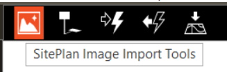
The Site Plan Import Tools are used to import a site plan and align this with the existing building. These tools function the same way that the floor plan import tools work.
The Site Plan Import Tools are used to create the building site features on the Drawing Canvas. They include tools to import and manipulate a Site Plan, place and configure the External Generators, and External Equipment, as well as the size and placement of the Shading features.
Site Tools
The Site Tools are used to create the building site features on the Drawing Canvas. They include tools to import and manipulate a Site Plan, place and configure the External Generators, and External Equipment, as well as the size and placement of the Shading features.
Site Plan Image Tools
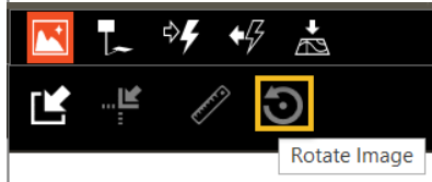
These tools are used to import a 2-D image file to be used as the basis for the site plan. Once the site plan image is selected, you are able to load the image by clicking the Load button. The image is processed while loading and is then applied to the Drawing Canvas. Once the image is loaded, you will be able to move the origin of the image using the Move Origin tool, move the image freely using the Move Image tool, and scale the image using the Scale Image tool. You will also be able to rotate the image using the Rotate Image tool or reset it to the conditions it was in after it was initially loaded with the Reset Image tool.
You are also able to remove the image from the Drawing Canvas by clicking the Unload button. Doing so will remove the image, but any traced features from the image will remain.
Selection Tool
The Select tool allows you to select or delete a site plan image. When selecting a site plan image you will also open the properties of that site plan.
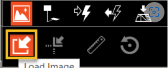
Load Image
The Load Image tool allows you to import an image into the project file that will be used for the site plan.
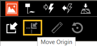
Move Origin
The Move Origin tool allows you to move the image by setting the building origin to the coordinates located on the site plan image. The tool sets the first point of
the building as the origin, this is determined in the Building section of the model. The second point is the corresponding point on the site plan.
Move Image
The Move tool allows you to move the image freely by selecting two distinct points on the Drawing Canvas.
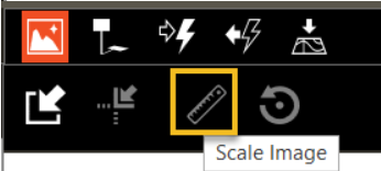
Scale Image
The Scale Image allows you to set the scale of the site plan image by comparison to a known dimension of the building. In order to do so, you will need to draw a dimension line on the building where the known dimension is. This line will help determine the scale for the site plan. The fixed starting point of the dimension line is where you first click. As you drag the mouse a dimension line will be displayed. When you click a second time to select the end of the dimension line, a “Dimension” dialog box will be displayed. The dialog box that appears will allow you to enter the known dimension and click OK. The site plan image will now match the scale of the building.
Rotate Image
The Rotate Image tool allows you to rotate the image around a selected point on the image. You will need to select one point on the 2-D trace over image. This point will be the center of rotation and is the first point of a line that can be rotated to align with the x-axis or y-axis. Then you will move the mouse and click again to create a line on the site image. This line could be the edge of the building that you want to align with the x-axis. Finally, the user will move the mouse causing the image to rotate around the center of rotation to a new orientation and clicks the mouse button on a point corresponding to where the image will rotate.
Reset Image
The Reset Image tool allows you to reset the trace over image state to the condition it was in immediately upon import.
Buildings
Shadings
The shadings section in the Site tree encompasses those elements which reduce the solar load of the modeled building by blocking out the sun.
Adjacent Building
When you select an adjacent building, you will be given access to the properties of that building. Each adjacent building on the site will have a separate entry in the tree. You will be able to rename the building General tab. On the Construction tab, you will be able to set the Name, Exterior Surface Construction library member, the Glazing Percentage and associated Glazing Construction library member for each adjacent building exterior wall, slab, and roof.
Another method of accessing the adjacent building properties is through the tree as well as through the Site Tools.
External Generators
External Generators include on-site power generating equipment including Photovoltaic, Wind Turbine, Internal Combustion Engine, and Combustion Turbine. These equipment types allow the energy model to account for energy generation to offset building energy use.
Photovoltaic
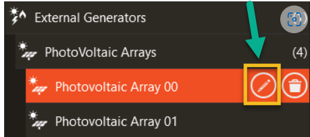
To add a photovoltaic array (solar panel), click Photovolatic Array from the External Generator Tools icon. Select the desired parameters, then place on the canvas. The photovoltaic arrays will appear on the left tree. If there is a large PV panel array for the site consider simplifying the model to a smaller number of larger panels to reduce calculation time while maintaining the same footprint and energy production.
If the panels need to go on top of a building ensure that the elevation is set to correspond to the rooftop.

PV panels will appear on the menu tree on the left after they are added to the file by the tool icon. Panel properties can be edited after creation by selecting the pencil icon associated with the menu tree item.
The energy generated from the PV panels needs to be setup in the Utility Rate to activate Net Metering or selling power back to the local Utility. See the Utility Rate section for details.
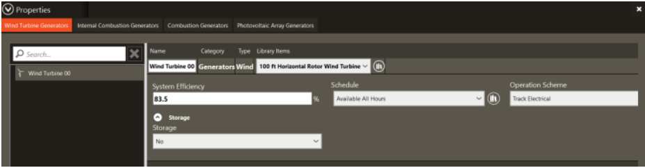
Wind Turbine
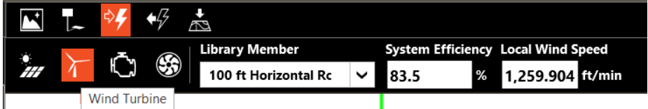
To add a wind turbine, click Wind Turbine, Select the desired parameters, then place on the canvas. The wind turbine(s) will appear on the left tree. To access the properties of a wind turbine, click the pencil icon next to the wind turbine name. In the properties window, the user may change the parameters of the wind turbine. After the Wind Turbines are added to the file, they can be viewed in the Create Site – 3D view mode.
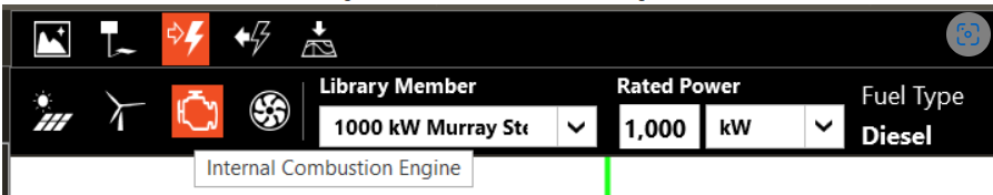
Internal Combustion Engine
To add an internal combustion engine, click Internal Combustion Engine, and select the desired parameters before placing the engine on the canvas. The internal combustion engine(s) will appear on the left tree. To access the properties of an internal combustion engine, click the pencil icon next to the internal combustion engine name.

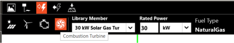
Combustion Turbine
To add a combustion turbine, click Combustion Turbine, select the desired parameters, then place on the canvas. The combustion turbine(s) will appear on the left tree. To access the properties of a combustion turbine, click the pencil icon next to the internal combustion engine name. In the properties window, the user may change the parameters of the internal combustion engine. Press F1 for parameter definitions.
External Equipment
External Equipment includes on-site power consuming equipment such as, Exterior Lights, Exterior Fuel Use Equipment, and Exterior Water Use Equipment. This equipment acts as an energy-consuming device based upon a time-of-day schedule.
These items are found under the External Equipment Tool tab. Clicking on this icon provides access to the Exterior Lights, Exterior Fuel Equipment, and Exterior Water Equipment.
Select all desired External Equipment, place them in the site map and they will appear in the Left hand Menu Tree. Clicking the pencil icon in the menu tree opens up the properties tab for editing.
Exterior Lights
The Exterior Lights object is used to model exterior lights for a building or site such as parking lot lights, illuminated sign lights, or façade lights. When selecting an exterior lights object in the tree or on the Drawing Canvas, you are able to access the object's properties, some of these include, Object Name Field, Maximum Power, and Utilization Schedule.
Name
This field allows you to give each object a specific name.
Maximum Power
This field is used to represent the maximum electrical input to exterior lighting fixtures which is then multiplied by a schedule fraction.
Utilization Schedule
A schedule will allow the exterior lights consumption to be operationally different, hour to hour as well as seasonally. Fractional values in the basic schedule will be applied to the design level field below.
Do not run when the Sun is up
This checkbox allows you to toggle on or off the ability to override the schedule and turn off the lights when the weather dictates that the Sun is up and the lights are not required.
Fuel Use Equipment
This object allows you to create a generic piece of equipment that uses a specified Fuel Type. The generic equipment will consume that fuel per the Maximum Power and Utilization Schedule.
Name
This field allows you to give each object a specific name.
Maximum Power
This field is used to represent the maximum power generated by the equipment. TRACE 3D Plus then uses this power value to calculate how much fuel would be consumed in order to generate this output. The resulting value is then multiplied by a schedule fraction to find the actual fuel use for that time step.
Fuel Type
This field designates the appropriate meter for the exterior fuel equipment. Valid fuel types are: Electricity, Natural Gas, Propane Gas, FuelOil#1, FuelOil#2, Diesel, Gasoline, Coal, Steam, District Heating, District Cooling, OtherFuel1 and OtherFuel2. The fuel type triggers the application of consumption amounts to the appropriate energy meters.
Utilization Schedule
A schedule will allow the fuel use equipment consumption to be operationally different, hour to hour as well as seasonally. Fractional values in the basic schedule will be applied to the design level field below.
Water Use Equipment
The Water Use Equipment is used to model objects that utilize water outside of the building. The properties available for these objects include Peak Flow Rate and Utilization Schedule. You are also able to configure auxiliary objects such as pumps, water collection, and storage.
Name
This field allows you to give each object a specific name.
Peak Flow Rate
Much like Maximum Power, the peak flow rate is used to represent the maximum hourly water use. This is then multiplied by a schedule fraction.
Utilization Schedule
A schedule will allow the consumption of the water use objects to be operationally different, hour to hour as well as seasonally. Fractional values in the basic schedule will be applied to the design level field below.
Pump
The Pump checkbox allows you to assign a pump to the Water Use Equipment and set the Rated Power Consumption which will operate per the assigned Utilization Schedule.
Rain Collector
The Rain Collector checkbox allows you to assign a rainwater collection system to the Water Use Equipment and set the Collector Surface Area and set a Loss Factor to this collection system.
Ground Water Well
The Ground Water Well checkbox allows you to assign a well system to the Water Use Equipment and set the Pump Rated Flow Rate and set a Pump Rated Power Consumption to this well system.
Water Storage
The Water Storage feature allows you to assign a water storage system to the Water Use Equipment and set the Maximum Capacity and an Initial Capacity.
Adjacent Building Drawing Tools
The drawing tools allow you to create an Adjacent Building for building shading. This can be used to either trace over a site plan image or to create the buildings free-hand. The tools include Rectangle and Polyline which allow you to set the perimeter of the adjacent building(s). Included with this tool set is the ability to set the footprint dimensions, the building Height, the Elevation of the building, the percent of that building that is glazed, and both the Exterior Construction library member as well as the Glazing Construction library member.
Rectangle Building
This tool allows you to create a square or rectangular building footprint by selecting just 2 points on the Drawing Canvas. You can also set the length and width of this shape using the appropriate fields in the Adjacent Building Drawing Tools toolbar.
Polyline
This tool allows you to create a building footprint of any desired shape. You will be able to set the length of a line using the appropriate fields in the Adjacent Building Drawing Tools toolbar.
Length
You are able to set the length (length along the X or horizontal axis for the rectangle tool or the length of the wall for the polyline tool) of the adjacent building.
Width
You are able to set the width (length along the Y or vertical axis for the rectangle tool) of the adjacent building. This property is disabled for the polyline tool.
Height
You are able to set the vertical height of the adjacent building.
Elevation
You are able to set how high off the ground this adjacent building will begin. This feature could be used to create a shading device such as a large billboard.
% Glazed
This field allows you to set the percentage of glazing on the adjacent building.
Exterior Construction Name
You are able to set the composition of the exterior walls for the adjacent building. Assigning these library members will impact the Solar Reflectivity, etc. of the exterior walls, which could impact the loading on the energy model.
Glazing Construction Name
This field gives you the ability to choose a glazing type from the Glazing library for the adjacent building which will impact the Solar Reflectivity, etc. of the building and could impact the loading on the energy model.
External Generators
This tool set allows users to place and configure objects such as Photovoltaic, Wind Turbine, Internal Combustion Engine, and Combustion Turbine.
Photovoltaic Array Tool
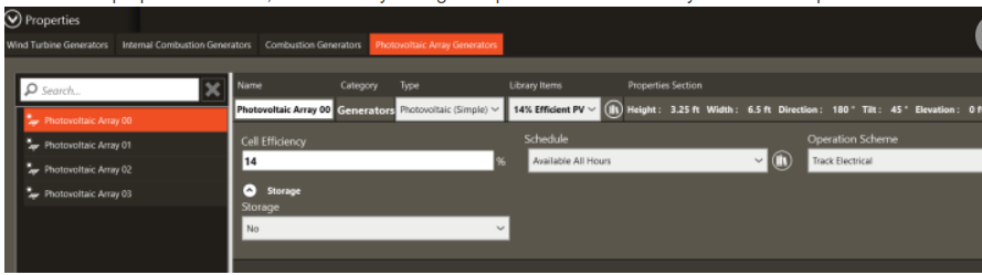
This tool gives you the ability to place a Photovoltaic Array on the building site. You will also be able to configure some of the properties such as Height, Width, Elevation, Direction and Tilt. You will also be able to set the Category as well as select the Library Member used for the energy model.
See Equipment Library for more information
Wind Turbine Tool
You are able to use this tool to locate and configure Wind Turbines on building sites. The configurable properties are System Efficiency and Local Wind Speed as well as the ability to select the Library Member.
See Equipment Library for more information
Internal Combustion Engine Tool
This tool gives you the ability to place and configure the properties for an Internal Combustion Engine-powered generator. The properties available to be configured through this tool are Rated Power and Fuel Type as well as the ability to select the Library Member. This field is read-only within the project and can only be modified within the object library.
See Equipment Library for more information
Combustion Turbine Tool
This tool gives you the ability to place and configure the properties for a Combustion Turbine power generator. The properties available to be configured through this tool are Rated Power and Fuel Type as well as the ability to select the Library Member. This field is read-only within the project and can only be modified within the object library.
See Equipment Library for more information
External Equipment Tools
This tool set allows you to place and configure objects such as Exterior Lights, Fuel-Use Equipment and Water-Use Equipment.
Exterior Light Tool
You are able to place exterior lights as well as set the Maximum Power and Utilization Schedule used to apply the hourly power value. You will also be able to apply the Don’t run when Sun is up override.
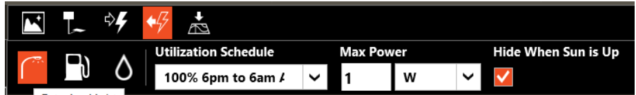
Exterior Fuel-Use Equipment Tool
This tool is used to place and configure equipment that will expend the specified fuel type according to a time-of-day schedule. You will also be able to set the hourly Maximum Power value, Fuel Type, and the Utilization Schedule.
Exterior Water-Use Equipment Tool
This tool is used to place and set the hourly Peak Flow Rate value as well as the Utilization Schedule used to apply the water usage rate value.
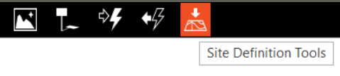
Site Definition Tools
This tool set allows you to define the site position and orientation. The included tools are Move Site, and Set Site North.
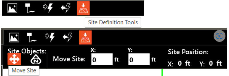
Move
This tool allows you to click and drag the entire site plan on the drawing canvas. Click once to select, then drag to the new position and click again to drop. The new X and Y origin coordinates can also be entered in the fields at the top of the canvas.
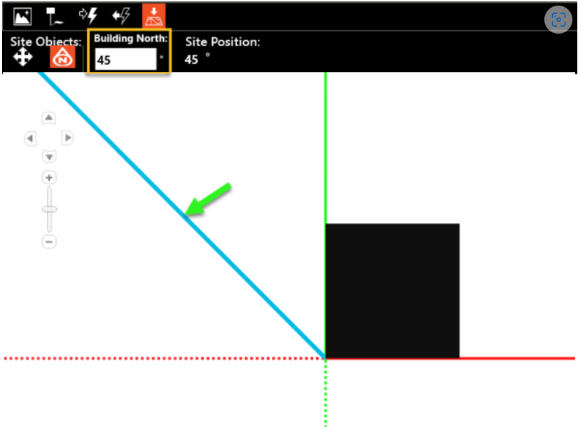
Set Site North
This tool allows you to change the definition of site north. By default, north is defined as straight up on the drawing canvas. The direction of north can be changed by entering the desired degrees of counter-clockwise rotation in the field at the top of the drawing canvas. A blue line will appear indicating the new north. This blue line will also appear in the 3D view and the canvas in Create Building.
Note: This rotation will not change the value of the entered direction in the Create Rooms section, nor does it appear listed in any of the output reports.
We recommend that you add a note in the Project Information section to remind yourself and others of the rotation.
Rotate
This tool allows you to freely rotate any site feature around a chosen axis.
Ground Plain Elevation
This tool allows you to freely increase or decrease the elevation of the site ground plain.
Site Drawing Canvas Tools
The Drawing Canvas tools are used to customize the look and feel of the Drawing Canvas as it is being used to create the building or building site.
Plan View
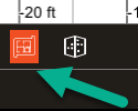
Full Building View
This button reverts the Drawing Canvas back to the Full Building view from the Plan View.
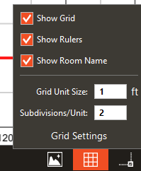
Grid Settings
This tool set allows you to toggle on and off the drawing grid, the rulers, or the building footprint.
Snap Settings
This set of tools allows you the ability to toggle on and off the following grid snap setting:
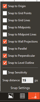
· Snap to origin
· Snap to grid
· Snap to sub-divided grid
· Snap to walls
· Snap to midpoints
· Snap to Midpoint lines
· Snap to endpoints
· Snap to wall projections
· Snap to parallel
· Snap to perpendicular (normal)
· Snap to common angles
· Snap to level outline
You are also able to change the grid sizing with the Grid Subdivisions field and customize the Snap distance.