Load/Airflows
Load/Airflows
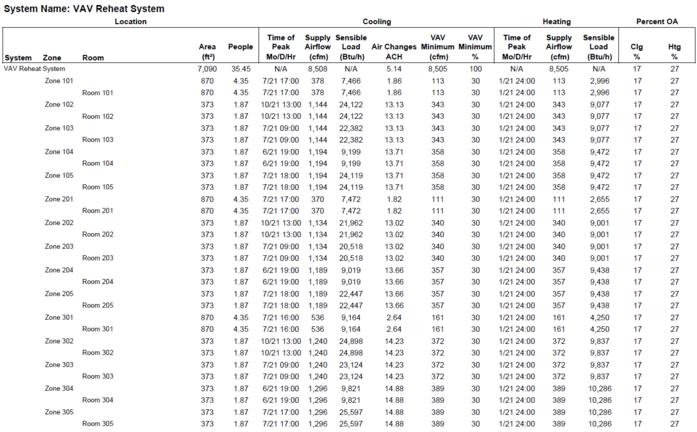
The Load/Airflows table provides the design sensible load, design supply air dry bulb, and design supply airflow of each room and zone. This table is useful for sizing supply diffusers to each room. The peak time comes from the load calculation. If the airflow to a room was hardset by the user, the hardset value will override the calculation. See the Zone Summary report for a different view for some of this information. The Load/Airflows section of the System Component Summary contains much of the same information.
Use Zone 101 for an example. The system named “VAV Reheat System” contains multiple zones, including Zone 101. Zone 101 contains one room named “Room 101”. If other rooms were contained, they would be indented under Zone 101 like Room 101. The floor area of Room 101 is 870 ft2. The time of the Zone 101’s peak cooling load was July 21 at 17:00 (5:00 pm). The design cooling airflow is 378 cfm. The design heating airflow is 30 % of 378 cfm, equal to 113 cfm. In this situation, a VAV Reheat System was used with a default minimum stop of 30 %.