Opaque Materials
Opaque Materials
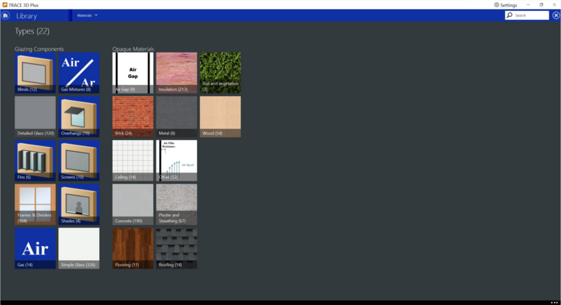
Opaque materials are materials that are used as layers in the creation of opaque constructions like walls, floors, and roofs. The following opaque material types exist in the material library:
Opaque materials defined with detailed properties
When an opaque material is defined with detailed properties to be used as a layer for the construction of a building surface, care should be taken to not attempt to model assemblies that were not included in the intended scope of applicability for the underlying heat transfer models. The building surface models are for normal applications to building energy efficiency where the main focus is on assemblies with some thermal resistance. Extremely thin and/or highly conductive material layers should be neglected from the construction rather than included because they will not contribute to the assembly’s overall thermal resistance or heat capacity. For some cases, thin and/or highly conductive materials are a serious problem for the heat transfer modeling and the values for thickness, conductivity, density and specific heat are checked for appropriateness. This check calculates the material’s thermal diffusivity from the inputs for conductivity, density, and specific heat and compares it to a maximum threshold of 1.E-5 m2 /s. If the diffusivity is above this threshold, then the program checks if the layer is sufficiently thick and may issue a warning if it is too thin and highly conductive. The absorptance values in this object impart surface properties to the construction and should be applied to the thermally significant inner and outer layers in the overall assembly. Attempting to trick the program by modeling thin “paint” layers to apply surface properties is not a good idea; the models were not intended to support such strategies.
The details screen for the following materials will display the same detailed opaque material properties: brick, ceiling, concrete, flooring, insulation, metal, plaster & sheathing, other, roofing and wood. Air gaps and soil and vegetation will have different properties.
Opaque materials defined with resistance only
When an opaque material is defined as a no mass material using only the thermal resistance, the details screen will display the resistance only opaque material properties.
Soil and Vegetation
This material must be used in order to simulate the green roof (EcoRoof) model. The material becomes the outside layer in a green roof construction. In the initial release of the green roof model, only one soils and vegetation material layer can be used per roof construction. In addition, the model has only been tested with the Conduction Transfer Function solution algorithm. This model was developed for low-sloped exterior surfaces (roofs). It is not recommended for high-sloped exterior surfaces 150 (e.g., walls).
The soil and vegetation library member detail screen will display the soil and vegetation properties.
Air Gaps
This material is used to describe the air gap in an opaque construction element. It assumes that air is sufficiently lightweight to require only an R-value. In addition, since it is not exposed to any external environment, surface properties such as absorptance are not necessary. Note that glazing constructions use a different material to describe the air between two glass layers (gas and gas mixture).
Thermal resistance is the only required field to define an air gap material.
|
Default value:
|
blank
|
|
Min & Max:
|
0 < x <= 100,000
|
|
Typical Range:
|
0.05 to 0.15 (m2K)/W; 0.5 to 2 (ft2•°F•hr)/Btu
|
|
Units:
|
(m2K)/W; (ft2•°F•hr)/Btu
|
Detailed opaque material properties
Properties for brick, ceiling, concrete, flooring, insulation, metal, plaster & sheathing, other, roofing and wood.
Roughness
This field defines the relative roughness of a particular material layer. This parameter only influences the convection coefficients, more specifically the exterior convection coefficient. The options are “Very Rough”, “Rough”, “Medium Rough”, “Medium Smooth”, “Smooth”, and “Very Smooth”.
Thickness
This should be the dimension of the layer in the direction perpendicular to the main path of heat conduction. This value must be a positive. Modeling layers thinner (less) than 0.003 m is not recommended; rather, add those properties to one of the adjacent layers.
|
Default value:
|
blank
|
|
Min & Max:
|
0 <= x <= 100,000
|
|
Typical Range:
|
N/A
|
|
Units:
|
mm; in
|
Conductivity
This field is used to enter the thermal conductivity of the material layer. Units for this parameter are W/(mK) or Btu/hr•ft•°F. Thermal conductivity must be greater than zero. Modeling layers with conductivity higher than 5.0 W/(mK) is not recommended.
|
Default value:
|
221 W/mK
|
|
Min & Max:
|
0 <= x <= 100,000
|
|
Typical Range:
|
N/A
|
|
Units:
|
W/mK; W/m°C; Btu/hr•ft•°F
|
Density
This field is used to enter the density of the material layer. Density must be a positive quantity.
|
Default value:
|
blank
|
|
Min & Max:
|
0 <= x <= 100,000
|
|
Typical Range:
|
N/A
|
|
Units:
|
kg/m3; lb/ft3
|
Specific heat
This field represents the specific heat of the material layer. Note that these units are most likely different than those reported in textbooks and references which tend to use kJ/(kg-K) or J/(g-K). The units were chosen for internal consistency within EnergyPlus™. Only values of specific heat of 100 or larger are allowed.
|
Default value:
|
blank
|
|
Min & Max:
|
100 <= x <= 100,000
|
|
Typical Range:
|
800-2000 J/(kgK)
|
|
Units:
|
J/(kgK); J/(kg°C); Btu/lb°F
|
Thermal absorptance
The thermal absorptance field represents the fraction of incident long wavelength radiation that is absorbed by the material. This parameter is used when calculating the long wavelength radiant exchange between various surfaces and affects the surface heat balances (both inside and outside as appropriate). For long wavelength radiant exchange, thermal emissivity and thermal emittance are equal to thermal absorptance. Values for this field must be between 0.0 and 1.0 (with 1.0 representing “black body” conditions). The default value for this field is 0.9.
Solar absorptance
The solar absorptance field represents the fraction of incident solar radiation that is absorbed by the material. Solar radiation includes the visible spectrum as well as infrared and ultraviolet wavelengths. This parameter is used when calculating the amount of incident solar radiation absorbed by various surfaces and affects the surface heat balances (both inside and outside as appropriate). If solar reflectance (or reflectivity) data is available, then absorptance is equal to 1.0 minus reflectance (for opaque materials).
|
Default value:
|
0.7
|
|
Min & Max:
|
0 <= x <= 1
|
|
Typical Range:
|
N/A
|
|
Units:
|
N/A
|
Visible absorptance
The visible absorptance field represents the fraction of incident visible wavelength radiation that is absorbed by the material. Visible wavelength radiation is slightly different than solar radiation in that the visible band of wavelengths is much narrower while solar radiation includes the visible spectrum as well as infrared and ultraviolet wavelengths. This parameter is used when calculating the amount of incident visible radiation absorbed by various surfaces and affects the surface heat balances (both inside and outside as appropriate) as well as the daylighting calculations. If visible reflectance (or reflectivity) data is available, then absorptance is equal to 1.0 minus reflectance (for opaque materials).
Resistance only opaque material properties
Roughness
This field defines the relative roughness of a particular material layer. This parameter only influences the convection coefficients, more specifically the exterior convection coefficient. The options are “Very Rough”, “Rough”, “Medium Rough”, “Medium Smooth”, “Smooth”, and “Very Smooth”.
Thermal resistance
This field is used to enter the thermal resistance (R-value) of the material layer.
|
Default value:
|
blank
|
|
Min & Max:
|
0 < x <= 100,000
|
|
Typical Range:
|
0.05 to 0.15 (m2K)/W; 0.5 to 2 (ft2•°F•hr)/Btu
|
|
Units:
|
(m2K)/W; (ft2•°F•hr)/Btu
|
Thermal absorptance
The thermal absorptance field represents the fraction of incident long wavelength radiation that is absorbed by the material. This parameter is used when calculating the long wavelength radiant exchange between various surfaces and affects the surface heat balances (both inside and outside as appropriate). For long wavelength radiant exchange, thermal emissivity and thermal emittance are equal to thermal absorptance. Values for this field must be between 0.0 and 1.0 (with 1.0 representing “black body” conditions).
Solar absorptance
The solar absorptance field represents the fraction of incident solar radiation that is absorbed by the material. Solar radiation includes the visible spectrum as well as infrared and ultraviolet wavelengths. This parameter is used when calculating the amount of incident solar radiation absorbed by various surfaces and affects the surface heat balances (both inside and outside as appropriate). If solar reflectance (or reflectivity) data is available, then absorptance is equal to 1.0 minus reflectance (for opaque materials).
|
Default value:
|
0.7
|
|
Min & Max:
|
0 <= x <= 1
|
|
Typical Range:
|
N/A
|
|
Units:
|
N/A
|
Visible absorptance
The visible absorptance field represents the fraction of incident visible wavelength radiation that is absorbed by the material. Visible wavelength radiation is slightly different than solar radiation in that the visible band of wavelengths is much narrower while solar radiation includes the visible spectrum as well as infrared and ultraviolet wavelengths. This parameter is used when calculating the amount of incident visible radiation absorbed by various surfaces and affects the surface heat balances (both inside and outside as appropriate) as well as the daylighting calculations. If visible reflectance (or reflectivity) data is available, then absorptance is equal to 1.0 minus reflectance (for opaque materials).
Soil and vegetation properties
Average height of plants
This field defines the height of plants in units of meters.
|
Default value:
|
0.2
|
|
Min & Max:
|
0.005 <= x <= 1
|
|
Typical Range:
|
N/A
|
|
Units:
|
m; ft
|
Ratio of soil covered by leaves
This is the projected leaf area per unit area of soil surface. This field is dimensionless and is limited to values in the range of 0.001 < LAI < 5.0. Default is 1.0. At the present time the fraction vegetation cover is calculated directly from LAI (Leaf Area Index) using an empirical relation. The user may find it necessary to increase the specified value of LAI in order to represent high fractional coverage of the surface by vegetation.
|
Default value:
|
1
|
|
Min & Max:
|
0.001 < x <= 5
|
|
Typical Range:
|
N/A
|
|
Units:
|
N/A
|
Leaf reflectivity
This field represents the fraction of incident solar radiation that is reflected by the individual leaf surfaces (albedo). Solar radiation includes the visible spectrum as well as infrared and ultraviolet wavelengths.
Leaf emissivity
This field is the ratio of thermal radiation emitted from leaf surfaces to that emitted by an ideal black body at the same temperature. This parameter is used when calculating the long wavelength radiant exchange at the leaf surfaces. Values for this field must be between 0.8 and 1.0 (with 1.0 representing “black body” conditions).
|
Default value:
|
0.95
|
|
Min & Max:
|
0.8 <= x <= 1
|
|
Typical Range:
|
N/A
|
|
Units:
|
N/A
|
Plant resistance to transport moisture
This field represents the resistance of the plants to moisture transport. Plants with low values of stomatal resistance will result in higher evapotranspiration rates than plants with high resistance.
|
Default value:
|
180
|
|
Min & Max:
|
50 <= x <= 300
|
|
Typical Range:
|
N/A
|
|
Units:
|
s/m; s/ft
|
Soil roughness
This alpha field defines the relative roughness of a particular material layer. This parameter only influences the convection coefficients, more specifically the exterior convection coefficient. A keyword is expected in this field with the options being “Very Rough”, “Rough”, “Medium Rough”, “Medium Smooth”, “Smooth”, and “Very Smooth” in order of roughest to smoothest options. Default is Medium Rough.
Soil thickness
This field characterizes the thickness of the material layer in meters. This should be the dimension of the layer in the direction perpendicular to the main path of heat conduction.
|
Default value:
|
0.1
|
|
Min & Max:
|
0.05 < x <= 0.7
|
|
Typical Range:
|
0.10m to 0.15m; 4in to 6in
|
|
Units:
|
m; ft
|
Dry soil conductivity
This field is used to enter the thermal conductivity of the material layer. Units for this parameter are W/(mK). Thermal conductivity must be greater than zero.
|
Default value:
|
0.35
|
|
Min & Max:
|
0.2 <= x <= 1.5
|
|
Typical Range:
|
0.3 to 0.5
|
|
Units:
|
w/mK; W/m°C; Btu/hr•ft•°F
|
Dry soil density
This field is used to enter the density of the material layer. Density must be a positive quantity. Typical soils range from 400 to 1000 (dry to wet).
Dry soil specific heat
This field represents the specific heat of the material layer. Note that these units are most likely different than those reported in textbooks and references which tend to use kJ/(kg-K) or J/(g-K). They were chosen for internal consistency within EnergyPlus™. Only positive values of specific heat are allowed.
|
Default value:
|
1200
|
|
Min & Max:
|
500 <= x <= 2000
|
|
Typical Range:
|
N/A
|
|
Units
|
J/(kgK); Btu/lb°F
|
Thermal absorptance
The thermal absorptance field represents the fraction of incident long wavelength radiation that is absorbed by the material. This parameter is used when calculating the long wavelength radiant exchange between various surfaces and affects the surface heat balances (both inside and outside as appropriate). For long wavelength radiant exchange, thermal emissivity and thermal emittance are equal to thermal absorptance. Values for this field must be between 0.0 and 1.0 (with 1.0 representing “black body” conditions).
|
Default value:
|
0.9
|
|
Min & Max:
|
0 <= x <= 1
|
|
Typical Range:
|
N/A
|
|
Units
|
N/A
|
Solar absorptance
The solar absorptance field represents the fraction of incident solar radiation that is absorbed by the material. Solar radiation includes the visible spectrum as well as infrared and ultraviolet wavelengths. This parameter is used when calculating the amount of incident solar radiation absorbed by various surfaces and affects the surface heat balances (both inside and outside as appropriate). If solar reflectance (or reflectivity) data is available, then absorptance is equal to 1.0 minus reflectance (for opaque materials).
Visible absorptance
The visible absorptance field represents the fraction of incident visible wavelength radiation that is absorbed by the material. Visible wavelength radiation is slightly different than solar radiation in that the visible band of wavelengths is much narrower while solar radiation includes the visible spectrum as well as infrared and ultraviolet wavelengths. This parameter is used when calculating the amount of incident visible radiation absorbed by various surfaces and affects the surface heat balances (both inside and outside as appropriate) as well as the daylighting calculations. If visible reflectance (or reflectivity) data is available, then absorptance is equal to 1.0 minus reflectance (for opaque materials).
|
Default value:
|
0.75
|
|
Min & Max:
|
0 <= x <= 1
|
|
Typical Range:
|
0.5 to 1
|
|
Units
|
N/A
|