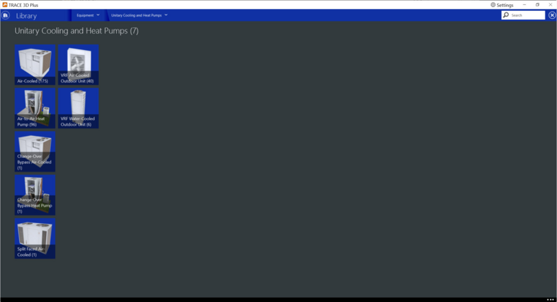
Trace 3D Plus
User Guide
 
×
 
 
Unitary Cooling and Heat Pumps


VRF Air-Cooled Outdoor Unit
 
VRF Water-Cooled Ourdoor Unit


Air-Cooled
The Air-cooled Self Contained Component simulates the performance of a DX cooling coil used in combination with a whole Air Cooled Self Contained Unit. It defines the Unitary Cooling section of the Air-cooled Self Contained Unit which resides in the Air-cooled and Self Contained Library.
The rated conditions for obtaining capacities, efficiencies, and the sensible heat ratio of the cooling coil component are the indoor dry-bulb temperature at 80˚F  (26.67˚C), wet bulb temperature at 67˚F (19.44˚C), and a condenser entering air temperature at 95˚F (35˚C).


Product Tab
 
Rated Cooling Capacity
Default: Auto sized
Typical Range: 20 to 70 tons
Min Max: 0 < X < 100,000,000,000,000
Units: W, kW, Btuh, Mbh, tons
This field specifies the rated cooling capacity of the self contained unit in cooling mode according the actual building cooling load.
 
Rated Full Load Energy Rate
Default: 3.77 COP
Typical Range: N/A
Min Max: 0.11 < X < 2,999,999,999
Units: COP; EER; KW/KW; KW/MBh; KW/ton; MBh/ton; therms/(ton-hr)
This field specifies the full load energy rate of the heat pump unit for rated conditions at the highest operating speed for cooling mode. The energy rate should account for the compressor, condenser fan, and accessories, but exclude the supply air fan.
 
Rated Airflow Rate
Default: Autosize
Typical Range: 4,000 to 35,000 CFM
Min Max: 0 < X < 100,000,000,000,000
Units: ACH; CFM; L/s; m^3/hr; m^3/s
This field specifies the rated airflow rate corresponding to the design cooling capacity. This design airflow rate is used to determine the airflow rates at various speed levels if they exist.
 
 
Cooling OA Minimum Temperature
Default: -13°F, -25°C
Typical Range: N/A
Min Max: -100,000,000,000,000 < X < 100,000,000,000,000
Units: °F, °C
This field defines the minimum outdoor air dry-bulb temperature where the cooling coil compressor turns off.
 
Condenser Type
Default: Air-Cooled
Types: Air-Cooled, EvaporativelyCooled
Min Max: N/A
Units: N/A
This field specifies the type of condenser applied to the self-contained unit.
 
Condenser Pump Rated Power
Default: 10W
Typical Range: N/A
Min Max: 0 - 100,000,000,000,000
Units: hp, kW, therms, W
This field specifies the rated power of the evaporative condenser water pump if an Evaporatively Cooled condenser is used. This value is used to calculate the power required to pump the water used to evaporatively cool the condenser inlet air.). This field is not used when Condenser Type is Air Cooled.
 
 
Hot Gas Retreat
Enable Hot Gas Reheat
Default: No
Typical Range: N/A
Min Max: N/A
Units: N/A
This field determines whether or not the Air to Air Heat Pump will model heat reclamation from the superheated refrigerant and gas leaving the compressor. The superheated refrigerant coil reheats the air downstream of the DX cooling coil.
 
Parasitic Electric Load
Default: 0
Typical Range: N/A
Min Max: 0 < X < 100,000,000,000,000
Units: hp, kW, W
This field specifies the parasitic electric load due to control valves or other devices specific to the hot gas reheat coil operation. The load is applied whenever the coil is heating the air. Note that the electric load is small and does not contribute to the reheat.
 
Heat Reclaim Efficiency
Default: 0
Typical Range: 25 to 30%
Min Max: 0 < X < 30
Units: hp, kW, W
This field defines the ratio of recovered waste heat from the superheated refrigerant gas to the total rejected waste heat from the heat pump (as if no heat reclamation occurred).
 
 
Dehumidification
Dehumidification Control Type
Default: None
Types: None, Cool Reheat
Min Max: N/A
Units: N/A
This field determines the type of dehumidification control. The following options are valid for this field:
None - meet sensible load only, no active dehumidification control. If the system control type is SingleZoneVAV then dehumidification control must be set to None.
If the dehumidification control type is specified as CoolReheat, the DX coil will cool beyond the dry-bulb temperature set point as required to meet the high humidity setpoint. The reheat coil will then heat the supply air back to dry bulb setpoint. In order to apply a dehumidification control strategy make sure to add a relative humidity sensor in the Configure Systems system schematic.
 
OA Coil Leaving Min
Default: 36°F
Types: N/A
Min Max:
Units: °F, °C
 
 
Condensate
Time for Condensate to Begin
Default: 0 s
Typical Range: N/A
Min Max:  0 < X < 100,000,000,000,000
Units: s
This field determines the nominal time after startup for condensate to begin leaving the coil’s condensate drain line at the coil’s rated airflow and temperature conditions. The nominal time is equal to the ratio of the energy of the coil’s maximum condensate holding capacity (J) to the coil’s steady-state latent capacity (W).
 
Evaporation Ratio
Default: 0
Typical Range: N/A
Min Max:  0 < X < 100,000,000,000,000
Units: N/A
This field determines the ratio of the initial moisture evaporation rate from the cooling coil (when the compressor first turns off) and the coil’s steady-state latent capacity at rated airflow and temperature conditions. A value of zero means the latent degradation model is disabled.
 
 
Basin and Crankcase Heater
Crankcase Heater Capacity
Default: 0 Btuh
Typical Range: N/A
Min Max:  0 < X < 100,000,000,000,000
Units: Btuh, kW, MBh, W
This field determines the compressor crankcase heater capacity. The crankcase heater is enabled for any time when the outdoor air dry bulb temperature is below the Crankcase Outdoor DB Limit and the compressor is not running. To simulate a unit without a crankcase heater, enter a value of 0.
 
Crankcase Outdoor DB Limit
Default: 50°F, 10°C
Typical Range: N/A
Min Max:  0 < X < 100,000,000,000,000
Units: °F, °C
This field determines the outdoor air dry-bulb temperature above which the compressor crankcase heater is disabled.


Curve Tab
 
Speed <X> Ref. Rated Clg Capacity
Default: 38 tons
Typical Range: N/A
Min Max:  0 < X < 100,000,000,000,000
Units: Btuh; kW; MBh; tons; W
This field defines the total, full load gross cooling capacity of the air-to-air cooling coil unit at rated conditions for speed <X> operation. Capacity should not account for supply air fan heat.
 
Speed <X> Ref. Rated Sensible Heat Ratio
Default: 0.7
Typical Range: N/A
Min Max:  0 < X < 1
Units: N/A
This field defines sensible heat transfer ratio (SHR = gross sensible cooling capacity divided by gross total cooling capacity) of the cooling coil unit at rated conditions for speed <X> operation. This value should be obtained from the Reference Unit data.
 
Speed <X> Ref. Rated Energy Rate
Default: 3.77 COP
Typical Range: N/A
Min Max:  0.11 < X < 1,000,000,000
Units: Units: Units: COP; EER; kW/kW; kW/MBh; kW/ton; MBh/ton; therms/(ton-hr)
This field defines the efficiency of the cooling coil unit at rated conditions for speed <X> operation. The input power includes power for the compressor(s), condenser fan and accessories, but does not include the supply air fan. The gross Reference Rated Energy Rate should not account for the supply air fan.
 
Speed <X> Ref. Rated Airflow
Default: 312,000 cfm
Typical Range: N/A
Min Max:  0.01 < X < 100,000,000,000,000
Units: Units: ACH; cfm; L/s; m^3/hr; m^3/s
Cooling coil at rated conditions for Speed <X> operation. The value entered here should be directly from the Reference Unit data, corresponding to the given cooling capacity and efficiency at the speed.
 
*See the Reference page for resources used in the help documentation.


Air-to-Air Heat Pump
 
The Air to Air Heat Pump equipment library member simulates the performance of the compressor, condenser, and evaporator in a heat pump system. If modeling a Packaged Terminal Heat Pump, which includes the supply fan, the Air to Air Heat Pump is considered a Heat Pump Component within its library member. Otherwise the Air to Air Heat Pump itself can be added to the system diagram of a new airside system (e.g. Single Duct VAV System) and modeled as one heat pump serving multiple spaces. In this case a fan equipment library member would also need to be added to the system diagram in Configure Systems.
The Air to Air Heat Pump houses a collection of performance curves in the Curve Tab which represents operation at the various speed levels. These curves are generated from Reference Unit catalog data and can include up to 10 speeds of operation. The rated conditions for obtaining the capacities, COPs, and SHRs are at an indoor dry bulb temperature of 80˚F (26.67˚C), wet bulb temperature of 67˚F (19.44˚C), and a condenser entering air temperature of 95˚F (35˚C).
The Rated Cooling Capacity and Rated Cooling Airflow Rate on the Product tab are the actual design cooling capacity and airflow rate present per the input building model. These rated capacities and airflows are used to determine the corresponding capacities and airflows at the various speed levels in simulation.


Product Tab
Note: The below default values are based on the “< 5 Ton Std Eff PTHP Comp, Cond, Evap” library member.
 
Rated Heating Capacity
Default: Auto Sized
Typical Range: N/A
Min Max:   0 < X < 100,000,000,000,000
Units: W; kW; Btuh; Mbh; Tons
This field specifies the rated heating capacity of the heat pump in heating mode according to the actual building heating load.
 
Rated Cooling Capacity
Default: Auto Sized
Typical Range: 7,000 – 240,000 Btuh
Min Max:   0 < X < 100,000,000,000,000
Units: W; kW; Btuh; Mbh; Tons
This field specifies the rated cooling capacity of the heat pump in cooling mode according the actual building cooling load.
 
Rated Cooling Full Load Energy Rate
Default: 3.77 COP
Typical Range: 2.9 – 3.2 COP
Min Max:   0.11 < X < 2,999,999,999
Units: COP; EER; KW/KW; KW/MBh; KW/ton; MBh/ton; therms/(ton-hr)
This field specifies the full load energy rate of the heat pump unit for rated conditions at the highest operating speed for cooling mode. The energy rate should account for the compressor, condenser fan, and accessories, but exclude the supply air fan.
 
Rated Heating Full Load Energy Rate
Default: 2.9 COP
Typical Range: N/A
Min Max:  0.11 < X < 1,000,000,000
Units: COP; EER; KW/KW; KW/MBh; KW/ton; MBh/ton; therms/(ton-hr)
This field specifies the full load energy rate of the heat pump unit for rated conditions at the highest operating speed for heating mode. The energy rate should account for the compressor, condenser fan, and accessories, but exclude the supply air fan.
 
Rated Heating Airflow Rate
Default: Auto Sized
Typical Range: N/A
Min Max: 0 < X < 100,000,000,000,000
Units: ACH; CFM; L/s; m3/hr; m3/s
This field specifies the rated airflow rate corresponding to the design heating capacity. This design airflow rate is used to determine the airflow rates at various speed levels if they exist.
 
Rated Cooling Airflow Rate
Default: Auto Sized
Typical Range: N/A
Min Max: 0 < X < 100,000,000,000,000
Units: ACH; CFM; L/s; m3/hr; m3/s
This field specifies the rated airflow rate corresponding to the design cooling capacity. This design airflow rate is used to determine the airflow rates at various speed levels if they exist.
 
Hot Gas Reheat
Enable Hot Gas Reheat
Default: No
Typical Range: N/A
Min Max: N/A
Units: N/A
This field determines whether or not the Air to Air Heat Pump will model heat reclamation from the superheated refrigerant and gas leaving the compressor. The superheated refrigerant coil reheats the air downstream of the DX cooling coil.
 
Parasitic Electric Load
Default: 0
Typical Range: N/A
Min Max: 0 < X < 100,000,000,000,000
Units: hp, kW, W
This field specifies the parasitic electric load due to control valves or other devices specific to the hot gas reheat coil operation. The load is applied whenever the coil is heating the air. Note that the electric load is small and does not contribute to the reheat.
 
Heat Reclaim Efficiency
Default: 0
Typical Range: 25% to 30%
Min Max: 0 < X < 30
Units: hp, kW, W
This field defines the ratio of recovered waste heat from the superheated refrigerant gas to the total rejected waste heat from the heat pump (as if no heat reclamation occurred).
 
Dehumidification
Dehumidification Control Type
Default: None
Typical Range: None, Cool Reheat
Min Max: N/A
Units: N/A
This field determines the type of dehumidification control. The following options are valid for this field:
None - meet sensible load only, no active dehumidification control. If the system control type is SingleZoneVAV then dehumidification control must be set to None. In order to apply a dehumidification control strategy make sure to add a relative humidity sensor in the Configure Systems system schematic.
If the dehumidification control type is specified as CoolReheat, the DX coil will cool beyond the dry-bulb temperature set point as required to meet the high humidity setpoint. The reheat coil will then heat the supply air back to dry bulb setpoint.
 
Condensate
Evaporation Ratio
Default: 0
Typical Range: N/A
Min Max: 0 < X < 100,000,000,000,000
Units: N/A
This field determines the ratio of the initial moisture evaporation rate from the cooling coil (when the compressor first turns off) and the coil’s steady-state latent capacity at rated airflow and temperature conditions. A value of zero means the latent degradation model is disabled.
 
Time for Condensate to Begin
Default: 0
Typical Range: N/A
Min Max: 0 < X < 100,000,000,000,000
Units: s
This field determines the nominal time after startup for condensate to begin leaving the coil’s condensate drain line at the coil’s rated airflow and temperature conditions. The nominal time is equal to the ratio of the energy of the coil’s maximum condensate holding capacity (J) to the coil’s steady-state latent capacity (W).
 
Crankcase Heater
Crankcase Outdoor DB Limit
Default: 50°F, 10°C
Typical Range: N/A
Min Max: 0 < X < 100,000,000,000,000
Units: °F; °C
This field determines the outdoor air dry-bulb temperature above which the compressor crankcase heater is disabled.
 
Crankcase Heater Capacity
Default: 0 W
Typical Range: N/A
Min Max: 0 < X < 100,000,000,000,000
Units: Btuh; kW; MBh; W
This field determines the compressor crankcase heater capacity. The crankcase heater is enabled for any time when the outdoor air dry bulb temperature is below the Crankcase Outdoor DB Limit and the compressor is not running. To simulate a unit without a crankcase heater, enter a value of 0.
 
Defrost Heating Mode
Defrost
Default: Resistive
Typical Range: Resistive, Reverse Cycle
Min Max: N/A
Units: N/A
This field determines the defrost strategy for melting frost that may accumulate on the condenser coil. The two methods for defrosting are Reverse Cycle and Resistive. The Reverse Cycle method means the heating cycle is periodically reversed in order to melt the frost on the condenser coil. If instead the resistive strategy is used, frost is melted using an electric resistance heater.
 
Resistive Heater Capacity
Default: Auto Sized
Typical Range: N/A
Min Max: 0 < X < 100,000,000,000,000
Units: Btuh; kW; MBh; tons, W
This field defines the capacity of the electric resistance heater if the Resistive method is chosen for the Defrost Heating Mode.
 
Defrost Control
Default: OnDemand
Typical Range: OnDemand, Timed
Min Max: N/A
Units: N/A
This field determines how often defrost control occurs via either the OnDemand or Timed method. If the OnDemand method is chosen the defrost time period is calculated based on outdoor humidity ratio. If instead the Timed method is chosen then the defrost time period is based on a fixed value whether or not frost has actually accumulated.
 
Defrost Time Fraction
Default: 0.058333
Typical Range: N/A
Min Max: 0 < X < 1,000,000,000,000,000
Units: N/A
This field determines the fractional amount of time the unit is in defrost mode if Timed Defrost Control has been selected.
 
Max ODB Limit
Default: 32°F, 0°C
Typical Range: N/A
Min Max: -13 < X < 100,000,000,000,000
Units: °F, °C
This field determine the outdoor dry bulb temperature above which the heat pump will no longer enable defrost mode. This field pertains to either the OnDemand or Timed Defrost Control Method.
 
Min. ODB Limit
Default: 17.6°F
Typical Range: N/A
Min Max: -13 < X < 100,000,000,000,000
Units: °F, °C
This field determines the temperature below which the compressor will no longer operate.
 
 
Curves Tab
Note: The below default values are based on the “< 5 Ton Std Eff PTHP Comp, Cond, Evap” library member.
 
Cooling Mode
Speed <X> Ref. Rated Clg Capacity
Default: 38 Tons
Typical Range: 0 < X < 100,000,000,000,000
Min Max: N/A
Units: Btuh; kW; MBh; tons; W
This field defines the total, full load gross cooling capacity of the air-to-air cooling coil unit at rated conditions for speed <X> operation. Capacity should not account for supply air fan heat.
 
Speed <X> Ref. Rated Airflow
Default: 12,000 cfm
Typical Range: N/A
Min Max: 0.01 < X < 100,000,000,000,000
Units: ACH; cfm; L/s; m3/hr; m3/s
This field defines the airflow rate across the cooling coil at rated conditions for Speed <X> operation. The value entered here should be directly from the Reference Unit data, corresponding to the given cooling capacity and efficiency at the speed.
 
Speed <X> Ref. Rated Sensible Heat Ratio
Default: 0.7
Typical Range: N/A
Min Max: 0 < X < 1
Units: N/A
This field defines sensible heat transfer ratio (SHR = gross sensible cooling capacity divided by gross total cooling capacity) of the cooling coil unit at rated conditions for speed <X> operation. This value should be obtained from the Reference Unit data.
 
Speed <X> Ref. Rated Energy Rate
Default: 3.77 COP
Typical Range: N/A
Min Max: 0.11 < X < 1,000,000,000
Units: COP; EER; kW/kW; kW/MBh; kW/ton; MBh/ton; therms/(ton-hr)
This field defines the efficiency of the cooling coil unit at rated conditions for speed <X> operation. The input power includes power for the compressor(s), condenser fan and accessories, but does not include the supply air fan. The gross Reference Rated Energy Rate should not account for the supply air fan.
 
 
Heating Mode
Speed <X> Ref. Rated Heating Capacity
Default: 38 tons
Typical Range: N/A
Min Max: 0 < X < 100,000,000,000,000
Units: N/A
This field defines the total, full load gross heating capacity of the air-to-air heating coil unit at rated conditions for speed <X> operation. The gross heating capacity should not account for the effects of supply air fan heat.
 
Speed <X> Ref. Rated Airflow
Default: 12,000 cfm
Typical Range: N/A
Min Max: 0.01 < X < 100,000,000,000,000
Units: ACH; cfm; L/s; m3/hr; m3/s
This field defines the airflow rate across the heating coil at rated conditions for speed <X> operation. The value entered here should be directly from the Reference Unit data, corresponding to the given heating capacity and efficiency at the speed.
 
Speed <X> Ref. Rated Energy Rate
Default: 3.77 COP
Typical Range: N/A
Min Max: 0.11 < X < 1,000,000,000
Units: Units: COP; EER; kW/kW; kW/MBh; kW/ton; MBh/ton; therms/(ton-hr)
This field defines the efficiency of the heating coil unit at rated conditions for speed <X> operation. The input power includes power for the compressor(s), condenser fan and accessories, but does not include the supply air fan. The gross Reference Rated Energy Rate should not account for the supply air fan.
 
*See the Reference page for resources used in the help documentation.


Change-Over Bypass Air-Cooled
The Change-Over Bypass Air-Cooled library member is a unitary piece of equipment that is used to model a change-over bypass variable air volume system. It is made up of several components, including a mixing box, DX cooling coil, heating coil, and a supply air fan. The unitary piece of equipment will condition one or more zones controlled by thermostats located in each zone. Though used as a variable air volume system, the system air flow rate through the supply fan is constant at all times whether in cooling or heating mode. Any excess airflow is simply bypassed back to the mixing box instead of supplying air to the system zones.
 
 
Product Tab
 
Operating Mode
Default: Highest Mode Priority
Typical Range: Highest Mode Priority, Cooling Priority, Heating Priority
Min Max: N/A
Units: N/A
This field specifies whether the unitary system will prioritize heating or cooling mode during operation.
If Cooling Priority is selected, the system operates to meet the cooling load if any zone served by this system requires cooling. If no zones require cooling, then the system operates in heating mode if needed.
If Heating Priority is selected, the system operates to meet the heating load if any zone requires heating. If no zones require heating, then the system operates in cooling mode if needed.
If Highest Mode Priority is selected, the system operates based on the maximum number of zones requiring either heating or cooling. If the number of zones requiring cooling is greater than the number of zones requiring heating, then the system operates in cooling mode. If the number of zones requiring heating is greater than the number of zones requiring cooling, then the system operates in heating mode. If the number of zones requiring cooling equals the number of zones requiring heating, then the largest combined load (i.e., the sum of the cooling loads for zones requiring cooling compared to the sum of the heating loads for zones that require heating) sets the cooling or heating operating mode for the system during that simulation timestep.
 
Supply Fan
Supply Air Fan Placement
Default: Blow Through
Typical Range: Blow Through, Draw Through
Min Max: N/A
Units: N/A
This field specifies where the supply fan is located within the unitary system. If Blow Through is selected, the supply fan is located upstream of the main cooling coil. Draw Through means the supply fan is located downstream of the main cooling coil.
 
Cycling Mode
Default: Cycling Fan
Typical Range: Cycling Fan, Continuous Fan
Min Max: N/A
Units: N/A
This field specifies whether the supply fan is allowed to turn off during simulation or if it must run continuously. A Cycling Fan means that the supply fan can only turn off when no cooling or heating is required for the system. If a Continuous Fan is selected this means the supply fan runs the entire time the system is scheduled to operate.   
 
Supply Fan Type
Default: Tube Axial Fan
Typical Range: Cycling Fan, Continuous Fan
Min Max: N/A
Units: N/A
This field determines the type of supply fan from the constant volume fans library to be modeled in the unitary piece of equipment. This will determine the corresponding Fan Full Load Energy Rate and Pressure Rise from the Fans library member.
 
Fan Full Load Energy Rate
Default: 0.00025 kW/cfm
Typical Range: N/A
Min Max: 0.0000001 < X < 100,000,000,000,000
Units: kW/cfm; kw/(cfm – inH2O); kW/(L/sec); W; W/((L/sec) – Pa); W/((m^3/sec) – Pa); W/cfm; W/(cfm-inH2O); W/(L/sec); W/(m^3/sec)
This field specifies the full load energy rate for the supply fan.
 
Pressure Rise
Default: 2 in H20
Typical Range: N/A
Min Max: 0 < X < 100,000,000,000,000
Units: in H20
This field specifies the total system pressure rise experienced by the fan at the design airflow rate and altitude-adjusted standard density of dry air at 68°F (20°C) dry bulb.
 
Outdoor Airflow Rate
Default: Auto Size
Typical Range: N/A
Min Max: 0 < X < 100,000,000,000,000
Units: ACH; cfm; L/s; m^3/hr; m^3/s
This field determines the outdoor air flow rate through the system in cooling and heating mode operation.
 
Unitary Cooling
Unitary Cooling Type
Default: Std Eff 1-Stg PTAC Comp, Cond, Evap
Typical Range: N/A
Min Max: N/A
Units: N/A
This field determines the Air-Cooled unitary equipment library member to be used in the Change-Over Bypass Air-Cooled equipment library member. This determines the DX cooling coil, compressor, and condenser characteristics to be used in the equipment.
 
Dehumidification Control Type
Default: None
Typical Range: None, Cool Reheat
Min Max: N/A
Units: N/A
This field determines the type of dehumidification control to be implemented:
None – The system meets the sensible load only. There is no active dehumidification control.
Cool Reheat – The system cools beyond the dry-bulb temperature set point as required to meet the maximum humidity set point and then reheats the supply air to meet the dry bulb temperature set point.
 
Minimum Leaving Coil Temperature
Default: 46.4°F, 8°C
Typical Range: N/A
Min Max: -100,000,000,000,000 < X < 100,000,000,000,000
Units: °F, °C
This field determines the minimum outlet air temperature leaving the system when in cooling mode. This must be less than or equal to the maximum outlet air temperature during heating mode.
 
Unitary Heating
Unitary Heating Type
Default: Electric
Typical Range: Electric, Gas, Steam, Water
Min Max: N/A
Units: N/A
This field defines the heating coil equipment fuel source type used in the Changeover Bypass Air Cooled unitary equipment.
 
Unitary Heating
Default: Electric Heating Coil
Typical Range: N/A
Min Max: N/A
Units: N/A
This field defines the Heating Coil equipment library member used in the Changeover Bypass Air Cooled unitary equipment.
 
Maximum Leaving Coil Temperature
Default: 122°F, 50°C
Typical Range: N/A
Min Max: -100,000,000,000,000 < X < 100,000,000,000,000
Units: °F, °C
This field determines the maximum outlet air temperature leaving the system when in heating mode. This must be greater than or equal to the minimum outlet air temperature during cooling mode.
 
*See the Reference page for resources used in the help documentation.


Change-Over Bypass Heat Pump
The Change-Over Bypass Heat Pump library member is a unitary heat pump piece of equipment that is used to model a change-over bypass variable air volume system that operates as a heat pump. It is made up of several components, including a mixing box, DX coil, and a supply air fan. The unitary piece of equipment will condition one or more zones controlled by thermostats located in each zone. Though used as a variable air volume system, the system air flow rate through the supply fan is constant at all times whether in cooling or heating mode. Any excess airflow is simply bypassed back to the mixing box instead of supplying air to the system zones.
To model a Change-Over Bypass Heat Pump first add a Changeover Bypass System from the Select Systems tab. Go to the Configure Systems tab and open the properties for the system. Navigate to the Components section and under Type select Change-Over Bypass Heat Pump.
 
 
Product Tab
 
Operating Mode
Default: Highest Mode Priority
Typical Range: Highest Mode Priority, Cooling Priority, Heating Priority
Min Max: N/A
Units: N/A
This field specifies whether the unitary system will prioritize heating or cooling mode during operation.
If Cooling Priority is selected, the system operates to meet the cooling load if any zone served by this system requires cooling. If no zones require cooling, then the system operates in heating mode if needed.
If Heating Priority is selected, the system operates to meet the heating load if any zone requires heating. If no zones require heating, then the system operates in cooling mode if needed.
If Highest Mode Priority is selected, the system operates based on the maximum number of zones requiring either heating or cooling. If the number of zones requiring cooling is greater than the number of zones requiring heating, then the system operates in cooling mode. If the number of zones requiring heating is greater than the number of zones requiring cooling, then the system operates in heating mode. If the number of zones requiring cooling equals the number of zones requiring heating, then the largest combined load (i.e., the sum of the cooling loads for zones requiring cooling compared to the sum of the heating loads for zones that require heating) sets the cooling or heating operating mode for the system during that simulation timestep.
 
Supply Fan
Supply Air Fan Placement
Default: Blow Through
Typical Range: Blow Through, Draw Through
Min Max: N/A
Units: N/A
This field specifies where the supply fan is located within the unitary system. If Blow Through is selected, the supply fan is located upstream of the main cooling coil. Draw Through means the supply fan is located downstream of the main cooling coil.
 
Cycling Mode
Default: Cycling Fan
Typical Range: Cycling Fan, Continuous Fan
Min Max: N/A
Units: N/A
This field specifies whether the supply fan is allowed to turn off during simulation or if it must run continuously. A Cycling Fan means that the supply fan can only turn off when no cooling or heating is required for the system. If a Continuous Fan is selected this means the supply fan runs the entire time the system is scheduled to operate.   
 
Supply Fan Type
Default: Tube Axial Fan
Typical Range: N/A
Min Max: N/A
Units: N/A
This field determines the type of supply fan from the constant volume fans library to be modeled in the unitary piece of equipment. This will determine the corresponding Fan Full Load Energy Rate and Pressure Rise from the Fans library member.
 
Fan Full Load Energy Rate
Default: 0.00025 kW/cfm
Typical Range: N/A
Min Max: 0.0000001 < X < 100,000,000,000,000
Units: kW/cfm; kw/(cfm – inH2O); kW/(L/sec); W; W/((L/sec) – Pa); W/((m3/sec) – Pa); W/cfm; W/(cfm-inH2O); W/(L/sec); W/(m3/sec)
This field specifies the full load energy rate for the supply fan.
 
Pressure Rise
Default: 2
Typical Range: N/A
Min Max: 0 < X < 100,000,000,000,000
Units: in H2O
This field specifies the total system pressure rise experienced by the fan at the design airflow rate and altitude-adjusted standard density of dry air at 68°F (20°C) dry bulb.
 
Outdoor Airflow Rate
Default: Auto Size
Typical Range: N/A
Min Max: 0 < X < 100,000,000,000,000
Units: ACH; cfm; L/s; m3/hr; m3/s
This field determines the outdoor air flow rate through the system in cooling and heating mode operation.
 
Heat Pump Type
Heat Pump Components
Default: 90.1-10 Min Thru-The-Wall ACHP SS <30MBh Cooling Mode
Typical Range: N/A
Min Max: N/A
Units: N/A
This field determines the Air-to-Air Heat Pump library member to be used in the Change-Over Bypass Heat Pump equipment library member. This determines the DX cooling coil, compressor, and condenser characteristics to be used in the equipment.
 
Dehumidification Control Type
Default: None
Typical Range: None, Cool Reheat
Min Max: N/A
Units: N/A
This field determines the type of dehumidification control to be implemented:
None – The system meets the sensible load only. There is no active dehumidification control.
Cool Reheat – The system cools beyond the dry-bulb temperature set point as required to meet the maximum humidity set point and then reheats the supply air to meet the dry bulb temperature set point.
 
Minimum Leaving Coil Temperature
Default: 46.4°F; 8°C
Typical Range: N/A
Min Max: -100,000,000,000,000 < X < 100,000,000,000,000
Units: °F, °C
This field determines the minimum outlet air temperature leaving the system when in cooling mode. This must be less than or equal to the maximum outlet air temperature during heating mode.
 
Maximum Leaving Coil Temperature
Default: 122°F; 50°C
Typical Range: N/A
Min Max: -100,000,000,000,000 < X < 100,000,000,000,000
Units: °F, °C
This field determines the maximum outlet air temperature leaving the system when in heating mode. This must be greater than or equal to the minimum outlet air temperature during cooling mode.
 
*See the Reference page for resources used in the help documentation.


Split Faced Air-Cooled
 
 
To model a Split Faced Air Cooled Coil in the model first select a DX system type through the Select Systems tab. Go to Configure Systems and navigate to the Properties of the selected system. In the Properties navigate to Components and expand the cooling coil component. Under Type change from Air Cooled to Split Faced Air-cooled and choose the appropriate Split Faced Air Cooled library member.
The Split Faced Air Cooled library member can be used to model DX units with two stages (two sets of cooling coils split horizontally) as well as an enhanced dehumidification mode. The library member curves section defines the overall performance for each stage and mode of operation. Split Faced Air Cooled units can have up to 2 stages of operation for each of the normal cooling mode and enhanced dehumidification mode.
For most cases the Rated Airflow will be the same for all stages and modes of operation associated with the Split Face Air Cooled unit. If there is bypass air specified for the coil the Rated Airflow will include both the bypassed airflow as well as airflow through the active coil.
The Split Faced Air Cooled unit requires entries for the Rated Cooling Capacity, Reference Rated Sensible Heat Ratio, Reference Rated Energy Rate, and the Reference Rated Airflow via the Curve tab. These 4 inputs are used to determine the coil performance at the rating point (air entering cooling coil at 80F DB/67F WB and air entering the condenser at 95F DB/75F WB).
The model requires five curves as follows:
1.          The Capacity Curve (function of temperature) is a biquadratic curve with two independent variables: wet-bulb temperature of the air entering the cooling coil, and dry-bulb temperature of the air entering the air-cooled condenser coil (wet-bulb temperature if modeling an evaporative-cooled condenser). The curve is normalized to 1 at 67F indoor wet-bulb temperature and 95F outdoor dry-bulb temperature. The output of this curve is multiplied by the Reference Rated Cooling Capacity to give the total cooling capacity at specific temperature operating conditions (i.e., at temperatures different from the rating point temperatures).
2.          The Capacity Airflow Curve (function of flow fraction) is a quadratic or cubic curve with the independent variable being the ratio of the actual air flow rate across the cooling coil to the rated air flow rate (i.e., fraction of full load flow). The curve is normalized to have the value of 1.0 when the actual air flow rate equals the rated air flow rate. The output of this curve is multiplied by the Reference Rated Cooling Capacity and the Capacity Curve (function of temperature) to give the gross total cooling capacity at the specific temperature and air flow conditions at which the coil is operating.
3.          The Ambient Relief Curve (function of temperature) is a biquadratic curve with two independent variables: wet-bulb temperature of the air entering the cooling coil, and dry-bulb temperature of the air entering the air-cooled condenser coil (wet-bulb temperature if modeling an evaporative-cooled condenser). The curve is normalized to 1 at 67F indoor wet-bulb temperature and 95F outdoor dry-bulb temperature. The output of this curve is multiplied by the rated Energy Input Ratio (inverse of the rated COP) to give the EIR at specific temperature operating conditions (i.e., at temperatures different from the rating point temperatures).
4.          The Power – Airflow Curve (function of flow fraction) is a quadratic or cubic curve with the independent variable being the ratio of the actual air flow rate across the cooling coil to the rated air flow rate (i.e., fraction of full load flow). The curve is normalized to have the value of 1.0 when the actual air flow rate equals the rated air flow rate. The output of this curve is multiplied by the rated EIR (inverse of the rated COP) and the Ambient Relief curve (function of temperature) to give the EIR at the specific temperature and air flow conditions at which the coil is operating.
5.          The Part Load Fraction Curve (function of part load ratio) is a quadratic or cubic curve with the independent variable being part load ratio (sensible cooling load / steady-state sensible cooling capacity). The output of this curve is used in combination with the rated EIR and Ambient Relief Curves to give the effective EIR for a given simulation timestep. The part load fraction (PLF) curve accounts for efficiency losses due to compressor cycling. The curve should be normalized to a value of 1.0 when the part-load ratio equals 1.0 (i.e., the compressor(s) run continuously for the simulation timestep).


Product Tab
Rated Cooling Capacity
Default: Auto Size
Typical Range: N/A
Min Max: 0 < X < 100,000,000,000,000
Units: W; kW; Btuh; Mbh; tons
This field specifies the total, full load gross cooling capacity (sensible plus latent) of the DX coil at rated conditions (air entering the cooling coil at 26.7 °C DB/19.4 °C WB, air entering the outdoor condenser coil at 35 °C DB/23.9 °C WB, and a cooling coil air flow rate defined by the rated air flow rate field). Capacity should be gross (i.e., the effect of supply air fan heat is not accounted for).
 
Rated Full Load Energy Rate
Default: 3.7 COP
Typical Range: N/A
Min Max: 0.11 < X < 2,999,999,999
Units: COP; EER; KW/KW; KW/MBh; KW/ton; MBh/ton; therms/(ton-hr)
The Rated Full Load Energy Rate is the ratio of the gross total cooling capacity to electrical power input of the DX cooling coil at rated conditions. The input power includes electric power for the compressor(s) and condenser fan(s) but does not include the power consumption of the supply air fan.
 
Condenser Type
Default: Air-Cooled
Typical Range: Air-Cooled, EvaporativelyCooled
Min Max: 0.11 < X < 2,999,999,999
Units: N/A
This field specifies the type of condenser applied to the Split Faced Air-Cooled unit.
 
 
Condenser Pump Rated Power (For Evaporatively Cooled Condenser)
Default: 0 W
Typical Range: N/A
Min Max: 0 < X < 100,000,000,000,000
Units: W; kW; hp; therms
This field specifies the rated power of the evaporative condenser water pump. This value is used to calculate the power required to pump the water used to evaporatively cool the condenser inlet air. This field is not used when Condenser Type = Air-Cooled.
 
Cycling Rate (For latent degradation model)
Default: 0 cycles/hr
Typical Range: 3 cycles/hr
Min Max:  -100,000,000,000,000 < X < 100,000,000,000,000
Units: cycles/hr; cycles/s
This field specifies the maximum on-off cycling rate for the compressor, which occurs at 50% run time fraction. A value of 0 means the latent degradation model is disabled.
 
Latent Time Constant (For latent degradation model)
Default: 0 s
Typical Range: 45 s
Min Max:  -100,000,000,000,000 < X < 100,000,000,000,000
Units: s
This field specifies the time constant for the cooling coil’s latent capacity to reach steady state after startup. A value of 0 means the latent degradation model is disabled.
 
 
Hot Gas Reheat
Enable Hot Gas Reheat
Default: No
Typical Range: N/A
Min Max:  N/A
Units: N/A
This field determines whether or not the Split Faced Air-Cooled unit will model heat reclamation from the superheated refrigerant and gas leaving the compressor. The superheated refrigerant coil reheats the air downstream of the DX cooling coil.
 
Heat Reclaim Efficiency
Default: 0%
Typical Range: 25 to 30%
Min Max:  0 < X < 30
Units: hp; kW; W
This field defines the ratio of recovered waste heat from the superheated refrigerant gas to the total rejected waste heat from the heat pump (as if no heat reclamation occurred).
 
Parasitic Electric Load
Default: 0
Typical Range: N/A
Min Max:  0 < X < 100,000,000,000,000
Units: hp; kW; W
This field specifies the parasitic electric load due to control valves or other devices specific to the hot gas reheat coil operation. The load is applied whenever the coil is heating the air. Note that the electric load is small and does not contribute to the reheat.
 
 
Dehumidification
Dehumidification Control Type
Default: None
Typical Range: None, Cool Reheat
Min Max: N/A
Units: N/A
This field determines the type of dehumidification control. The following options are valid for this field:
None - meet sensible load only, no active dehumidification control. If the system control type is SingleZoneVAV then dehumidification control must be set to None.
If the dehumidification control type is specified as CoolReheat, the DX coil will cool beyond the dry-bulb temperature set point as required to meet the high humidity setpoint. The reheat coil will then heat the supply air back to dry bulb setpoint. In order to apply a dehumidification control strategy make sure to add a relative humidity sensor in the Configure Systems system schematic.
 
Condensate
Time for Condensate to Begin (For latent degradation model)
Default: 0 s
Typical Range: 1000 s
Min Max:  0 < X < 100,000,000,000,000
Units: s
This field determines the nominal time after startup for condensate to begin leaving the coil’s condensate drain line at the coil’s rated airflow and temperature conditions, starting with a dry coil. The nominal time is equal to the ratio of the energy of the coil’s maximum condensate holding capacity (J) to the coil’s steady-state latent capacity (W). A value of 0 means the latent degradation model is disabled.
 
Evaporation Ratio (For latent degradation model)
Default: 0
Typical Range: 1.5
Min Max:  0 < X < 100,000,000,000,000
Units: N/A
This field determines the ratio of the initial moisture evaporation rate from the cooling coil (when the compressor first turns off) and the coil’s steady-state latent capacity at rated airflow and temperature conditions. A value of 0 means the latent degradation model is disabled.
 
 
Basin and Crankcase Heater
Crankcase Heater Capacity
Default: 0 Btuh
Typical Range: N/A
Min Max:  0 < X < 100,000,000,000,000
Units: Btuh; kW; MBh; W
This field determines the compressor crankcase heater capacity. The crankcase heater is enabled for any time when the outdoor air dry bulb temperature is below the Crankcase Outdoor DB Limit and the compressor is not running. To simulate a unit without a crankcase heater, enter a value of 0.
 
Crankcase Outdoor DB Limit
Default: 50°F, 10°C
Typical Range: N/A
Min Max:  0 < X < 100,000,000,000,000
Units: °F, °C
This field determines the outdoor air dry-bulb temperature above which the compressor crankcase heater is disabled.


Curve Tab
 
Speed <X> Ref. Rated Clg Capacity
Default: 38 tons
Typical Range: N/A
Min Max:  0 < X < 100,000,000,000,000
Units: Btuh; kW; MBh; tons; W
This field specifies the total, full load gross cooling capacity (sensible plus latent) of the DX coil at rated conditions (air entering the cooling coil at 26.7 °C DB/19.4 °C WB, air entering the outdoor condenser coil at 35 °C DB/23.9 °C WB, and a cooling coil air flow rate defined by the rated air flow rate field) for speed <X> operation. Capacity should be gross (i.e., the effect of supply air fan heat is not accounted for).
 
Speed <X> Ref. Rated Airflow
Default: 0 cfm
Typical Range: N/A
Min Max:  0.01 < X < 100,000,000,000,000
Units: ACH; cfm; L/s; m3/hr; m3/s
This field defines the airflow rate across the cooling coil at rated conditions for Speed <X> operation. The gross rated total cooling capacity, gross rated SHR and gross rated COP should be performance information for the unit with air entering the cooling coil at 26.7 °C DB/19.4 °C WB, air entering the outdoor condenser coil at 35 °C DB/23.9 °C WB, and the rated air volume flow rate defined here.
 
Speed <X> Ref. Rated Condenser Flow (For Evaporatively Cooled Condenser)
Default: 0 cfm
Typical Range: N/A
Min Max:  0.01 < X < 100,000,000,000,000
Units: ACH; cfm; L/s; m3/hr; m3/s
This field specifies the air volume flow rate entering the evaporative condenser coil if an evaporatively cooled condenser has been selected. This value is used to calculate the amount of water used to evaporatively cool the condenser inlet air. This field is not used when Condenser Type = Air Cooled.
 
Speed <X> Ref. Rated Sensible Heat Ratio
Default: 1
Typical Range: N/A
Min Max:  0 < X < 1
Units: N/A
This field defines sensible heat transfer ratio (SHR = gross sensible cooling capacity divided by gross total cooling capacity) of the cooling coil at rated conditions for speed <X> operation at rated conditions (air entering the cooling coil at 26.7 °C DB/19.4 °C WB, air entering the outdoor condenser coil at 35 °C DB/23.9 °C WB, and a cooling coil air flow rate defined by the Ref. Rated Airflow field). Both the sensible and total cooling capacities used to define the Rated SHR should be gross (i.e., the effect of supply air fan heat is not accounted for).
 
Speed <X> Ref. Rated Energy Rate
Default: 3 COP
Typical Range: N/A
Min Max:  0.11 < X < 1,000,000,000
Units: COP; EER; kW/kW; kW/MBh; kW/ton; MBh/ton; therms/(ton-hr)
This field defines the efficiency of the cooling coil at rated conditions for speed <X> operation (ratio of gross total cooling capacity to electrical power input). The input power includes power for the compressor(s), condenser fan and accessories, but does not include the supply air fan. The gross Reference Rated Energy Rate should not account for the supply air fan.
 
Speed <X> Bypass Airflow
Default: 0%
Typical Range: 0 to 100%
Min Max:  -100,000,000,000,000 < X < 100,000,000,000,000
Units: %
This field specifies the fraction of the Rated Air Volume Flow Rate which bypasses the active cooling coil for the performance mode. The remaining portion of the flow should be between 300 to 450 cfm/ton (0.00004027 m3/s and .00006041 m3/s per watt) of Reference Rated Cooling Capacity for this performance mode. For DOAS applications the remaining portion of Rated Air Volume Flow Rate should be between 125 to 250 cfm/ton (0.00001677 m3/s and 0.00003355 m3/s per watt) of Reference Rated Cooling Capacity. This is used to model face-split coils on multi-stage units or bypass dampers. If total flow rate varies during simulation, the same fraction is always bypassed. For a multi-stage face-split coil in which stage 1 is 60% of total capacity, this field would be set to 40% for the Stage 1 performance and set to 0% for the Stage 1+2 performance. For a DX system which activates a bypass damper for improved dehumidification, this field would be set to 0% for normal mode performance and set to something greater than 0% for enhanced dehumidification mode performance.
 
Speed <X> Evap PreClg Pad Effectiveness (For Evaporatively Cooled Condenser)
Default: 1
Typical Range: N/A
Min Max: 0 < X < 10
Units: N/A
This field specifies the effectiveness of the evaporative condenser, which is used to determine the temperature of the air entering the outdoor condenser coil as follows:
T cond inlet = (T wb, o) + (1 − EvapCondEffectiveness) (T db, o − T wb, o)
where
Tcondinlet = the temperature of the air entering the condenser coil  
Twb,o = the wet-bulb temperature of the outdoor air  
Tdb,o = the dry-bulb temperature of the outdoor air
The resulting condenser inlet air temperature is used by the Capacity Curve (function of temperature) and the Ambient Relief Curve (function of temperature). This field is not used when Condenser Type = Air Cooled. To specify an air-cooled condenser, simply specify AirCooled in the Condenser Type field. In this case, the Capacity Curve (function of temperature) and the Ambient Relief Curve (function of temperature) input fields for the equipment should reference performance curves that are a function of outdoor dry-bulb temperature.
If attempting  to model an evaporatively-cooled condenser and performance curves are available that are a function of the wet-bulb temperature of air entering the condenser coil, then specify Condenser Type = EvaporativelyCooled and the evaporative condenser effectiveness value should be entered as 1.0. In this case, the Capacity Curve (function of temperature) and the Ambient Relief Curve (function of temperature) input fields for the equipment should reference performance curves that are a function of the wet-bulb temperature of air entering the condenser coil.
If attempting to model an air-cooled condenser that has evaporative media placed in front of it to cool the air entering the condenser coil, then the user should specify Condenser Type = EvaporativelyCooled. The appropriate evaporative effectiveness for the media should also be entered. In this case, the Capacity Curve (function of temperature) and the Ambient Relief Curve (function of temperature) input fields for the equipment should reference performance curves that are a function of outdoor dry-bulb temperature. Be aware that the evaporative media will significantly reduce the dry-bulb temperature of the air entering the condenser coil, so the Capacity and Ambient Relief Curves must be valid for the expected range of dry-bulb temperatures that will be entering the condenser coil.
 
 
*See the Reference page for resources used in the help documentation.